If either rx_footer or rx_checksum matches, the block is considered complete. If neither is present, the received data will be processed after the timeout period (though a timeout error will occur).
If rx_checksum returns a fixed value, it functions the same as rx_footer .
However, for clarity and context, it’s more appropriate to use rx_footer when referring to an end-of-block character.
I have done some quick tests now and it worked right away as a drop in replacement. Awesome!
So many more options to play with from here. ![]()
uartex:
  rx_footer: "\r" # Termination character

text_sensor:
  - platform: uartex
    id: "uart_readline"
    lambda: |-
      return std::string(reinterpret_cast<const char*>(data), len);
2 Likes
Great! If you have any other questions or need help, feel free to post here.
Do you have any plans to implement some more robust error checks in addition to add and xor like eg CRC-16-CCITT or some similar CRC-16 in the future?
Because there are so many different checksum methods for CRC16, it’s too extensive to include every checksum as an option. For now, I’ve only added the simple and common ones. However, by using lambda, you can utilize any checksum you want.
If you can tell me the common CRC16 checksum you need, I might be able to add it.
Yes, there are many different CRC-16 around, and from a perspective to use this component to connect to some existing device, your approach to support lambda for mor complex error checking makes total sense.
My first thought when discovered your component was however the “opposite”.
I have made some small projects in the garden there I’m using wired RS485 to not have to rely on wifi for sending data between the boards.
Your component already have the most bells and whistles I can think of, but with built in support for some kind of the more common CRC-16 variants, it will be so quick and easy and have everything needed to set up some pretty good home made communications without “thinking”.
Seen from this “reversed” use case I don’t think the specific variant of CRC-16 is that important.
Earlier mentioned CRC-16-CCITT looks quite robust and common and was also taken as the example in Ben Eaters really great video How do CRCs work?
If you don’t think implementing some kind of CRC-16 to the component is the right way for you, maybe consider to at least create a lambda example that can be used right away. That would be helpful for a lot of people I believe.
I really hope this component will be a part of the official ESPHome as handling serial communications is a really white spot here.
(Jeez, this got long…)
Thank you for your detailed feedback!
I’ll make sure to include the CRC16 checksum in the future.
Here is a simple lambda function example for calculating the checksum.
I’ll also update the documentation with usage examples later.
  rx_checksum2: !lambda |-
    uint16_t crc = 0;
    uint16_t poly = 0x1021;
    for (int i = 0; i < len; i++)
    {
        crc = crc ^ ((uint16_t)(data[i]) << 8);
        for (uint8_t j = 0; j < 8; j++)
        {
            if (crc & 0x8000) crc = (crc << 1) ^ poly;
            else crc <<= 1;
        }
    }
    return { (uint8_t)(crc >> 8), (uint8_t)(crc) };
1 Like
Hi.
Have error when compile:
src/esphome/components/uartex/uartex_device.cpp: In function 'bool esphome::uartex::check_value(uint16_t, uint8_t, const uint8_t*, uint16_t)':
src/esphome/components/uartex/uartex_device.cpp:252:18: error: expected ')' before 'len'
  252 |     if (index < 0 len || index >= len) return false;
      |        ~         ^~~~
      |                  )
Compiling .pioenvs/test-hum/src/esphome/core/log.cpp.o
*** [.pioenvs/test-hum/src/esphome/components/uartex/uartex_device.cpp.o] Error 1
========================== [FAILED] Took 5.21 seconds ==========================
ESPHome version 2025.3.3
Config uartex:
uart:
  rx_pin: GPIO3
  tx_pin: GPIO1
  baud_rate: 9600
  data_bits: 8
  parity: NONE
  stop_bits: 1

external_components:
  - source: github://eigger/espcomponents/@latest
    components: [ uartex ]
    refresh: always

uartex:
  rx_timeout: 10ms
  tx_delay: 50ms
  tx_timeout: 500ms
  tx_retry_cnt: 3

  rx_header: [0x55, 0x00]
  rx_footer: [0x03, 0x07, 0x00]
  tx_header: [0x55, 0x00]
  tx_footer: [0x00, 0x06, 0x00]

#  rx_checksum: add
#  tx_checksum: add

  version:
    disabled: False
  error:
    disabled: False
  log:
    disabled: False
Can you like to try again? There was an error that was committed by mistake, and I’ve fixed it.
Upon checking again, it turns out that the release branch should be compiled, but the main branch is being compiled instead. I will look into it.
Work! Thanks!
========================= [SUCCESS] Took 44.55 seconds =========================
1 Like
Hello eigger again. A really cool project that saved me days of development.
The question is, is it possible to specify the length of rx_length in the sensor? I will explain my request. Now, with the help of your project, I’m completing the local control of the MTS DTMS-705 humidifier (aka Daichi). He has all the controls in 12 characters, and he already gives temperature and humidity in 15 characters. Apparently, the MTS programmers couldn’t handle the fact that this data is not in the original application ![]()
If you set rx_length: 15 parsing starts to work extremely unstable. If you do not set rx_length, you will not be able to poll the device correctly. He gives the whole survey in one long line.
Does your protocol include a header (start string) or a terminator character (end marker)?
Currently, rx_length is a shared configuration parameter used for receiving data, and it cannot directly define the exact sensor message length.
If your device uses a fixed start or end marker, that would help separate and parse the data more reliably.
If possible, could you please share the following:
- A sample packet from the sensor (the 15-character string with temperature and humidity)
- A command example used to communicate with the sensor (the 12-character control command)
With that information, I can check if it’s possible to optimize the setup for your device.
Thanks for quick reply.
Example temp: 55 aa 03 07 00 08 0a 02 00 04 00 00 00 19 3a. Its rx
Example command on: 55 aa 00 06 00 05 01 01 00 01 01 0e. Its tx
Example status on: 55 aa 03 07 00 05 01 01 00 01 01 12. Its rx
Header: 55 aa for all.
He havent terminator ![]()
Did you add the checksum? I assume your last value is the add checksum.
Can you try like this?
uartex:
#...
  rx_header: [0x55, 0xaa]
  rx_checksum: add
  tx_header: [0x55, 0xaa]
  tx_checksum: add

button:
  - platform: uartex
    name: "Command"
    command_on:
      data: [0x00, 0x06, 0x00, 0x05, 0x01, 0x01, 0x00, 0x01, 0x01]
Good day. A few years ago, I made such a design.
The sensor, which consists of an arduino nano, DHT11 and a LORA-UART module, is located at a distance of 2500 meters, the receiver is LORA-UART + EP8266 with ESPHOME.
esphome:
  name: lora
  includes:
    - uart_read_line_sensor.h

esp8266:
  board: esp01_1m

# Enable logging
logger:
    level: DEBUG
    hardware_uart: UART1


uart:
  id: uart_bus
  tx_pin: GPIO0
  rx_pin: GPIO02
  baud_rate: 9600
  data_bits: 8
  parity: NONE
  stop_bits: 1

sensor:
  - platform: custom
    lambda: |-
      auto my_custom_sensor = new UartReadLineSensor(id(uart_bus));
      App.register_component(my_custom_sensor);
      return {my_custom_sensor->temperature_sensor, my_custom_sensor->tuer_sensor};
    sensors:
      - name: "Temperatupe"
        id: dlu_term
        unit_of_measurement: "°C"
        accuracy_decimals: 0
        icon: mdi:home-thermometer
      - name: "Humidity"
        id: dlu_humi
        accuracy_decimals: 0
        unit_of_measurement: "%"
        icon: mdi:water-percent
my_custom_sensor.h
#include "esphome.h"

class MyCustomSensor : public PollingComponent, public Sensor, public UARTDevice {
 public:
  MyCustomSensor(UARTComponent *parent) : PollingComponent(15000), UARTDevice(parent) {}
  Sensor *dlotem_sensor = new Sensor();
  Sensor *dlohum_sensor = new Sensor();


  void setup() override {
  }

  void update() override {
    // This is the actual sensor reading logic.
  String line = Serial.readStringUntil('\n');
  String t = line.substring(1, 6);
  String h = line.substring(7, 12);
  float dlotem = t.toFloat();
  float dlohum = h.toFloat();
  dlotem_sensor->publish_state(dlotem);
  dlohum_sensor->publish_state(dlohum);
  dlotem = 0;
  dlohum = 0;
  t = "";
  h = "";


  }

};
If you go to the web interface, it looks like this.
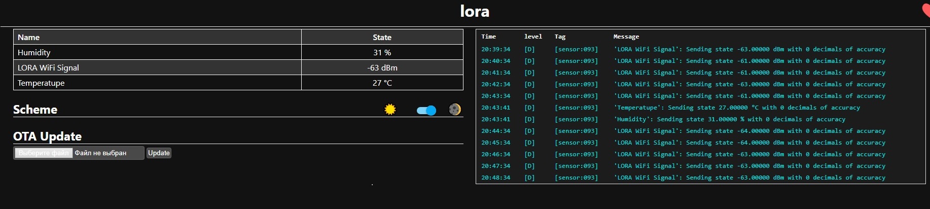
In HA lovelace, it looks like this.
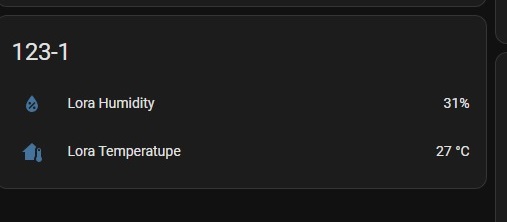
This design is then used in automation with notification. For two weeks I have been trying to remake this construction using external_components:. All I have managed to do is output the string in the form in which it is transmitted by arduino. But I cannot figure out how to parse it and bring it back to the form it was before. Tell me, how can I remake this using external_components:?
Hi andrei58
Can you try like this?
esphome:
  name: lora

esp8266:
  board: esp01_1m

# Enable logging
logger:
    level: DEBUG
    hardware_uart: UART1


uart:
  id: uart_bus
  tx_pin: GPIO0
  rx_pin: GPIO02
  baud_rate: 9600
  data_bits: 8
  parity: NONE
  stop_bits: 1


external_components:
  - source: github://eigger/espcomponents
    components: [ uartex ]
    refresh: always

uartex:
  rx_timeout: 10ms
  rx_footer: "\n"

  version:
    disabled: False
  error:
    disabled: False
  log:
    disabled: False

sensor:
  - platform: uartex
    name: "Temperatupe"
    id: dlu_term
    unit_of_measurement: "°C"
    accuracy_decimals: 0
    icon: mdi:home-thermometer
    state_number: !lambda |-
      if (len <= 6) return NAN;
      String str(to_ascii_string(data, len).c_str());
      return str.substring(1, 6).toFloat();

  - platform: uartex
    name: "Humidity"
    id: dlu_humi
    accuracy_decimals: 0
    unit_of_measurement: "%"
    icon: mdi:water-percent
    state_number: !lambda |-
      if (len <= 12) return NAN;
      String str(to_ascii_string(data, len).c_str());
      return str.substring(7, 12).toFloat();
Hello. Yes!!! It works. Thank you very much, I wouldn’t have done it myself. Thank you.
I’m glad I could help! If you ever have any questions or need, feel free to ask. ![]()
Hi Eigger,
Thank you very much for this component. It’s probably exactly what I’ve been looking for. However, at the moment I’m still at a bit of a loss as to how to configure the sensor for my application.
My current status looks like this:
external_components:
  - source: github://eigger/espcomponents@latest
    components: [ uartex ]
    refresh: always


uartex:
  rx_timeout: 10ms
  tx_delay: 50ms
  tx_timeout: 500ms
  tx_retry_cnt: 3

  rx_header: [0xF2, 0xF2]
  rx_footer: [0x7E]
  tx_header: [0xF1, 0xF1]
  tx_footer: [0x7E]
I get the following as a return from it:
[09:58:40][D][uartex:208]: Write array-> F1F10700077EF1F10700077E(12)
[09:58:40][D][uart_debug:176]: >>> 0,7,126
[09:58:40][D][uart_debug:176]: <<< 242,242,37,2,3,61,103,126,242
[09:58:40][D][uart_debug:176]: <<< 242,38,2,2,129,171,126,242,242
[09:58:40][D][uart_debug:176]: <<< 39,2,2,129,172,126,242,242,40
[09:58:40][D][uart_debug:176]: <<< 2,0,0,42,126,242,242,1,3
											           B1 B2
[09:58:40][D][uart_debug:176]: <<< 3,57,7,71,126
							      B3 B4
I would like to use bytes B1-B4 for the sensor. The payload starts with byte 1 (1) &2 (3). The sensor should display (byte 3 * 256 + byte 4) → 3 * 256 + 57 = 825. Could you help me with this?
Hi StefanSch
I don’t understand how the value in "Write array-> F1F10700077EF1F10700077E(12)" becomes >>> 0, 7, 126.
In the logs like [09:58:40][D][uart_debug:176]: <<< 242,242,37,2,3,61,103,126,... — are these values ASCII?
Can you explain the protocol format of the raw data being received?
I’m having trouble understanding the structure of the data protocol you’re using for receiving data.