Sounds like you’re getting on top of this. But if the chip on the front board handles the touch buttons and sliding lever, wouldn’t this also handle the leds on the touch sliding lever? You’re the one with the multimeter right now, though 
We’re all amateurs but together we’re pretty stubborn! 

Definitely, the chip handles the lighting of the front panel.
The ESP32 tells the front panel what the lamp brightness is, and the panel lights up the slider bar accordingly. Those LEDs are not directly controlled by the ESP32.
I see. So maybe one of the five leads is just unused if the I2C theory sticks. I want to go home to my lamp…  Looking forward to updates, Maurice!
Did some more measurements on the GPIO outputs for the white light. Funny results…
100% warm light (horizontal = brightness, vertical = voltage output)
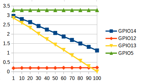
75% warm light

50% warm light

25% warm light

0% warm light (so 100% cool light)

100%, 75% and 50% follow a pattern, however at 25% something drastically different showed up and at 0% I saw something that looked a bit like the 50% measurements, only with some ports swapped.
So conclusion at this point is: need input 
I’ll do some more measurements on other percentages, especially to find out what happens around the turning point at 25%.
1 Like
Did a load of extra measurements and I think that I’ve got enough now to make the white light mode work. There’s some funny business going on in how to steer the LEDs in that modus, but I think all of the icky bits are in view now. Going to code a light component for ESPHome tomorrow, which includes this new knowledge.
As for I2C on the front panel: I uploaded a firmware witn support for it, but that one does not see devices on the bus:
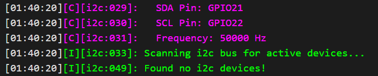
This is using the default pins for I2C. Since it is possible on ESP32 to assign different pins for the protocol, this does not fully strike the I2C route. When I’m done with the light, I might have to hookup a logic analyzer to the front panel bus, to see what’s going on there.
How did you implement the I2C? Could there be something with the frequency?
I can try some other frequencies, although I think the default 50kHz should be fine.
BTW, here’s a translated piece of info about the front panel chip:
Shanghai ChipON Microelectronics Technology Co., Ltd. (ChipON) recently launched the MCU KF8TS2716 that integrates control and touch. It integrates a RISC instruction core with independent intellectual property rights, 1040(1024+16)×8-bit RAM, 8K×16-bit program memory, and a wealth of peripherals: sixteen-channel 12-bit ADC, one SSCI (I2C/SPI) , 8x8 LED driver, etc.
The chip can connect up to 22 capacitive touch buttons, and supports 3mm thick acrylic plates and 5mm glass (ceramic) covers. It provides high-performance sensing in applications of various covering materials and thicknesses, which can protect keys from external interference and prevent false triggering. High reliability, strong anti-interference ability, I/O port can withstand 8KV electrostatic interference and 4.2KV rapid pulse interference.
KF8TS2716’s touch application development kit ChipON TSTool provides two touch algorithms, including general-purpose and waterproof. Customers can easily observe the change characteristics of the touch buttons and adjust the algorithm parameters according to different touch button conditions, which greatly shortens the development time of the product. ChipON also provides DEMO boards and sample programs according to customer requirements.
KF8TS2716 is an industrial-grade MCU with high immunity to electromagnetic interference. And it has lower power consumption, with a working voltage of 2.0~5.5V, which can be used in battery-powered applications.
After doing some more tracing on the main board, I found some ports that were possible I2C candidates. And after some experimentation with these ports, I now see this during startup of the device 

So, I can “ping” the device, which is likely the front panel.
Time to investigate the logic-level signals to see what the ESP32 and front panel are talking about!
Great! Did you have a look inside the original firmware? I think that I saw a I2C.c object in there, but I can’t confirm it before I get back home. Maybe that can give us some clues to the setup.
I have not looked at the original firmware at all. It’s quite the binary blob I presume, so it’s hard to get useful information out of it. But I still got one lamp in the original state, so I’ll pull down the firmware from that one, and see what I can learn from it.
Here’s one thing that I don’t mind getting rid of.
I always presumed that only my phone app would connect to the outside world, and that all settings and updates would run via that app.
However, this is what the original firmware boot messages show:
[20:27:07]08:00:06.160 [I] ots: de.ots.io.mi.com resolved to 3.126.247.75.
[20:27:07]08:00:06.160 [I] ots: ots connect 3.126.247.75::443...
[20:27:07]08:00:06.160 [I] tls: connect to server Mijia Cloud, domain is 3.126.247.75, port is 443.
I pulled the firmware from the device and am now sifting through it using a hex editor. So far no interesting stuff found, except for a bit of a happy thing: I don’t like the lamp connecting to some cloud, but at least the certificate for the HTTPS connection is stored in the firmware. +1 for that.
For the front panel controls, the range of events that can be triggered is as follows:
On/Off button
- code 100: button touch (always triggered, also for long touch)
- code 101: button short touch release
- code 102: button long touch start
- code 103: button long touch ongoing (event is triggered repeatedly, about 1 / second)
- code 104: button long touch release
Color button
- code 200: button touch (always triggered, also for long touch)
- code 201: button short touch release
- code 202: button long touch start
- code 203: button long touch ongoing (event is triggered repeatedly, about 1 / second)
- code 204: button long touch release
Brightness bar
The bar reports touch positions 1 - 20, which related to brightness values 1 - 100.
I don’t know a specific event code for these, possibly the codes are simply 1 - 20.
The output on the device’s console simply does not mention these as event codes.
But once I get to inspecting the I2 data, it should not be hard to relate the slider touch events to these touch position values.
Example touch button sequences
Example log data for a touch sequence
[22:14:16]05:14:16.050 [I] touch btn evt=200 - touch
[22:14:16]05:14:16.350 [I] touch btn evt=201 - short touch release
Example log data for a long touch
[22:15:25]05:15:24.630 [I] touch btn evt=200 - touch
[22:15:26]05:15:25.630 [I] touch btn evt=202 - long touch start
[22:15:26]05:15:25.990 [I] touch btn evt=204 - long touch release
Example log data for a very long touch sequence
[22:11:16]05:11:16.290 [I] touch btn evt=200 - touch
[22:11:17]05:11:17.290 [I] touch btn evt=202 - long touch
[22:11:18]05:11:18.290 [I] touch btn evt=203 - long touch ongoing
[22:11:19]05:11:19.290 [I] touch btn evt=203 - long touch ongoing
[22:11:20]05:11:20.260 [I] touch btn evt=204 - long touch release
1 Like
Out of curiosity; did you look at v.41 or the newer v.42? As mentioned earlier it is several good reasons to get ESPHome working. There is also a good reason for blocking internet access per device that wants to call home giving up all kinds of information. HA and local control is king, everything else is for the emperor
The console logging shows [20:27:01]MIIO APP VER: 2.0.6_0030 during boot up. I don’t have v41 or v42 apparently. The app shows the device as up-to-date when checking the firmware.
It differs from which server you’re connected to.
V.30 has LAN control but gave me some pesky connectivity errors in HA.
V.41 broke LAN control.
V.42 is a version that restores LAN control, but it is a “special” version that you only can get to download if Yeelight white lists your MI ID.
And you never get to update the FW again from this version if you like to have LAN control.
I can confirm pesky connectivity errors on V.30. Just one extra reason to work on a replacement firmware. Thanks for clearing up the versions.
For me, LAN control was also broken, because it also got removed from the smartphone app, which apparently disabled the LAN control along the way on my V.30 device. I could install an older apk file of the app to get the functionality back, but that all feels wrong. Being stuck to an app version and/or a firmware version is a Bad Thing.
BTW: I created a repo for the code that I’ve come up with so far. RGB is fully functional and the temperature-based lighting is partly working. I have to implement 6 different temperature zones, which all have their own GPIO output logic. So for 2/ 6 are done.
The code is definitely not yet production-ready, so currently I would advice against uploading it to a device.
2 Likes
The white light code is now ready.
Next thing is to go back to the RGB code. It is functional and already looks quite good, but especially in the colors towards white, I see some differences between my output and the original light. So another round of taking measurements coming up, to calibrate my RGB code.
1 Like
Yes, confirmed! The front panel talks I2C to the ESP32. I soldered some leads to the board and linked them up to a logic analyzer with Sigrok, and on a button push I see some hopeful stuff going on. No concrete results yet, but certainly a fun thing to report.

Experimenting with various functions, I found that the ESP32 must be the I2C master. When there is an event on the front panel to be communicated to the ESP32, the panel pulls an interrupt line low to signal that it wants the I2 master to send a read request. That way it can dump its event information to the ESP32.
That makes the pins for the front panel flat cable connector as follows:

I can now create some dumps and see if I can make sense of the protocol.
Update: yes I can
I finished my analysis on the I2C bus traffic that I captured, and I think that I’ve got the command set complete now. I’ve documented it in my github repo: i2c_commands.txt
Interesting thing: the device address of the front panel is 0x2C, however the device that I found before using ESPHome was on address 0x10. So there might be two I2C busses active on the ESP32, or there is a sneaky component between the panel and the ESP32 which modifies the signals (like a multiplexer or so). The latter doesn’t really make sense to me for a circuit like this, so let’s see if I can find another bus active.
Update: yes I can
I traced the SDA/SCL/INT pins of the front panel connector back to their ESP32 GPIO’s. The image from above now contains the GPIO mapping as well. After providing two busses to the ESPHome config, I got the following boot messages:

Bingo!
6 Likes
mmakaay has done a great job here and he has done almost all the heavy lifting by himself rather fast I will say. I think that we can wait a little bit longer for the moment of glory
2 Likes