Hi everyone, I’m working on a project with an ESP32 to measure bidirectional DC current (charge/discharge) up to about 200A.
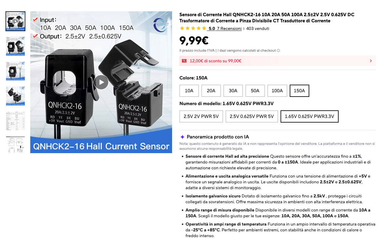
I’m considering using the Hall‑effect clamp sensor shown in the attachment, but I’m not completely sure whether it’s suitable for this kind of application. I also suspect that the ESP32 will need additional hardware (probably an external ADC like ADS1115) to read the sensor output correctly.
Has anyone here already built a similar high‑current DC monitoring setup with an ESP32?
Any advice on sensor choice, wiring, or signal conditioning would be really appreciated.
It has voltage output, so the 2.5V ±0.625V model should work with Esp32 without additional hardware. ADS1115 would give better resolution though.
Some Esp32 variants ADC perform poorly >3.0V.
Thanks for the clarification.
Just to confirm: I’m planning to use the QNHCK2‑16 100A – 2.5V ±0.625V (PWR 5V) model.
I will pass only the battery positive cable through the split‑core ring, since the sensor is bidirectional and should detect both charging and discharging current on the same line.
Again you mentioned 200A but getting the 100A model. It make no sense going under size. How did you arrive at that decision. Something is missing here. You need to look at the span (total range of output from the picks and how the ADC takes and outputs the corresponding DC voltage for measurement.
It is true , but I took into account the fact that I have a 200 A battery and a maximum current that I can measure of about 60 A , so for informational purposes I had written 200A . The choice will always fall into the 100A model.
Okay, that info is what helps with giving you the correct info then. So based on that 60A average high draw with a 100A current clamp for higher possible draws (this is also known as head space) short of a “direct short” on the battery will work fine.
“Time for the purchase” means you need it tomorrow and Amazon didn’t have it for one-day-delivery?
Any similar bidirectional hall clamp should be ok.
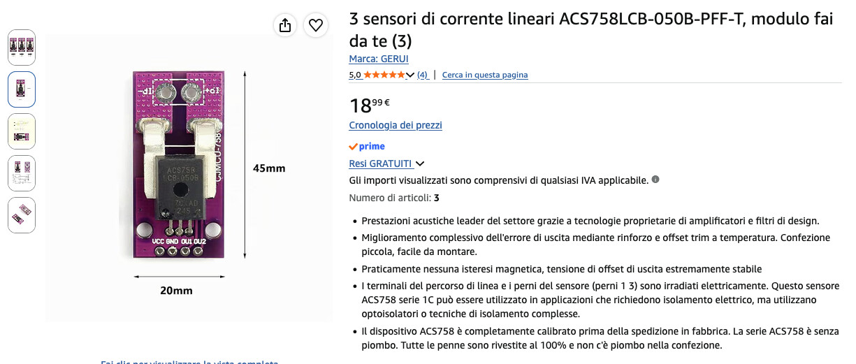
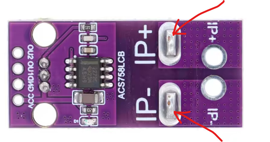
Also ACS758 (100B/150B/200B) is popular and readily available.
Hello I had seen it but it seems to me that it is not a hall sensor. How should it be connected in battery unlike the previous sensor? I see it has + and - to connect to the battery ? I would like to attach it to a lifepo5 51,20v battery that at the clamps because of the charge of the SCC would fluctuate up to almost 58 v
It is definitely hall sensor.
You connect IP+ to the battery positive and IP- to the load side positive.
So it’s on single wire, just like you would connect fuse. (and you should have fuse)
Your battery voltage doesn’t matter here.
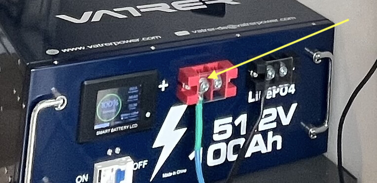
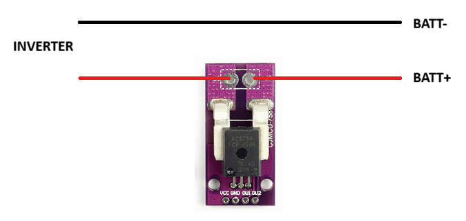
So, if you look at the photos I should connect the +p to the photo where you see the battery there is also a positive with free bolt, after the p- to the inverter in the positive ?? The path that does the positive to date is that it starts from the battery, passes through a thermal magnet and then goes directly to the inverter in its positive.
I hope I explained myself well.
From the scheme it seems that the cable must stop to go from hole and exit ??? Similar to a shunt that connects to the negative ?? Because if it would be absurd, connect a 16 mm2 cable in such a small hole !