I have been a happy user of Hörmann’s own HOR 1-HCP option relay with a Shelly Plus 1 for a while. It works, but it is a dumb toggle: a pulse on a relay contact, one feedback input, no real position, no light, no vent position. When the hoermann_hcp component landed in ESPHome and spoke Modbus straight to the motor’s bus, I wanted to try that for sure. It is now running on my ProMatic 4 at home.
The component needs an adapter: RS485 transceiver, a buck converter for the roughly 25 V on the bus, and of course an ESP32. Not sure how everyone else is hooking that up; I made a small carrier PCB and a printed case for mine, which I wanted to share here.
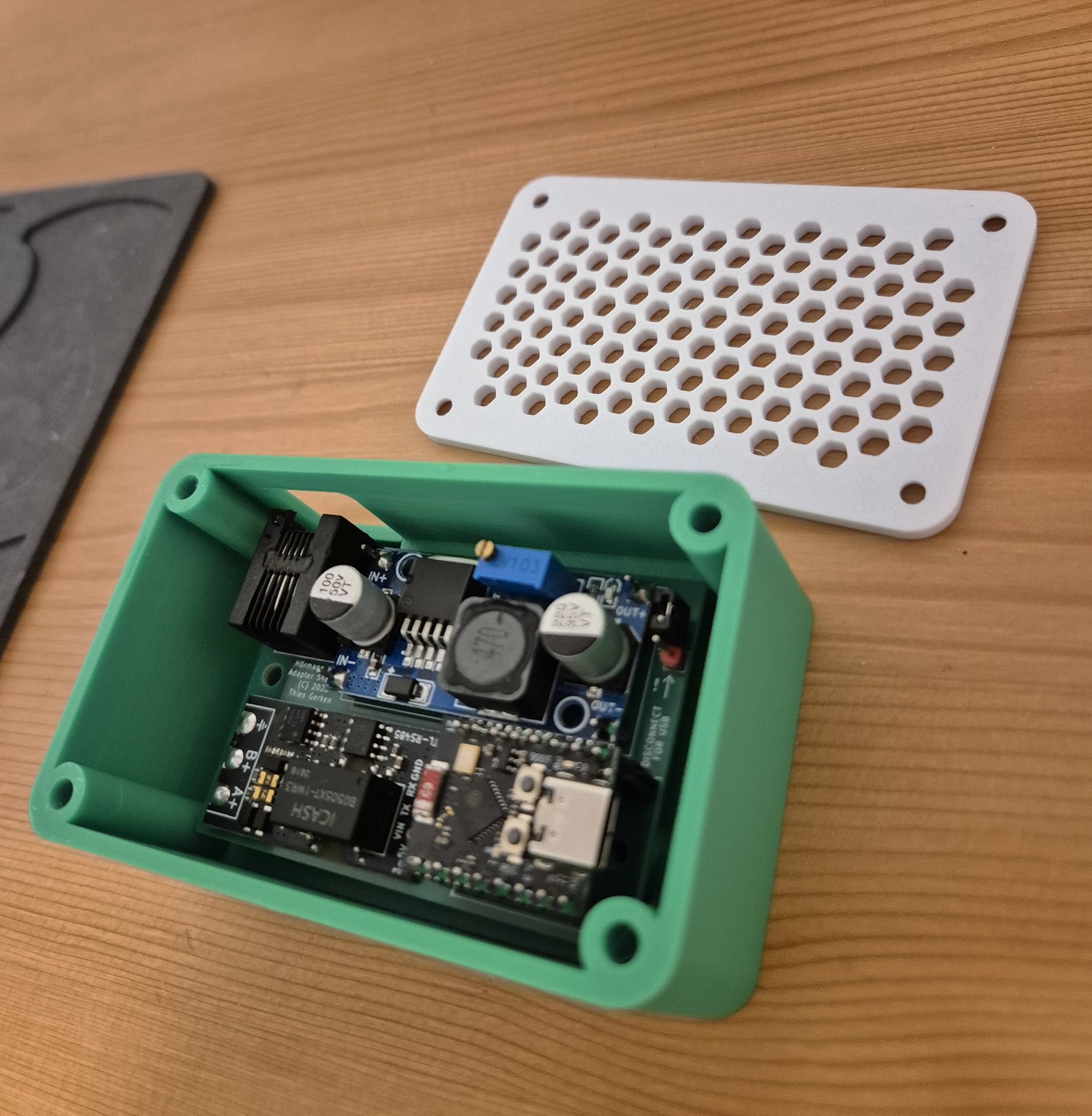
What it is
A 65 × 44.5 mm two-layer carrier for three cheap modules:
- ESP32-C3 SuperMini, socketed
- LM2596 HW-411 buck module, adjusted to 5.0 V before it goes on the board
- isolated TTL-to-RS485 module with automatic direction control and 120 Ω already on it
- 6P6C jack sitting flush with the board edge, so the cable from the motor plugs straight in
There is a jumper between the buck output and the ESP32’s 5 V pin. The SuperMini has no diode there, so USB and the converter must never feed that rail at the same time. The silkscreen says so next to the jumper.
The enclosure is parametric build123d: tray plus a vented lid, M3 heat-set inserts. It reads the board outline and hole positions directly from the PCB source, so the two cannot drift apart.
Repo
MIT License. It has the KiCad project, the gerbers, the STLs, the ESPHome config, and the design notes. The KiCad and CAD files are generated by Python scripts, so board and case stay in sync.
Cheers!