Local Thermia iTec integration with ESPHome / Home Assistant

I’ve been working on a fully local Home Assistant integration for my Thermia iTec XTR M, using the internal communication bus instead of Thermia Online / Thermia Connect.

The goal was to build a local integration for Home Assistant without using the rather expensive Thermia Online / Thermia Connect gateway — and for the fun of reverse engineering it, of course.

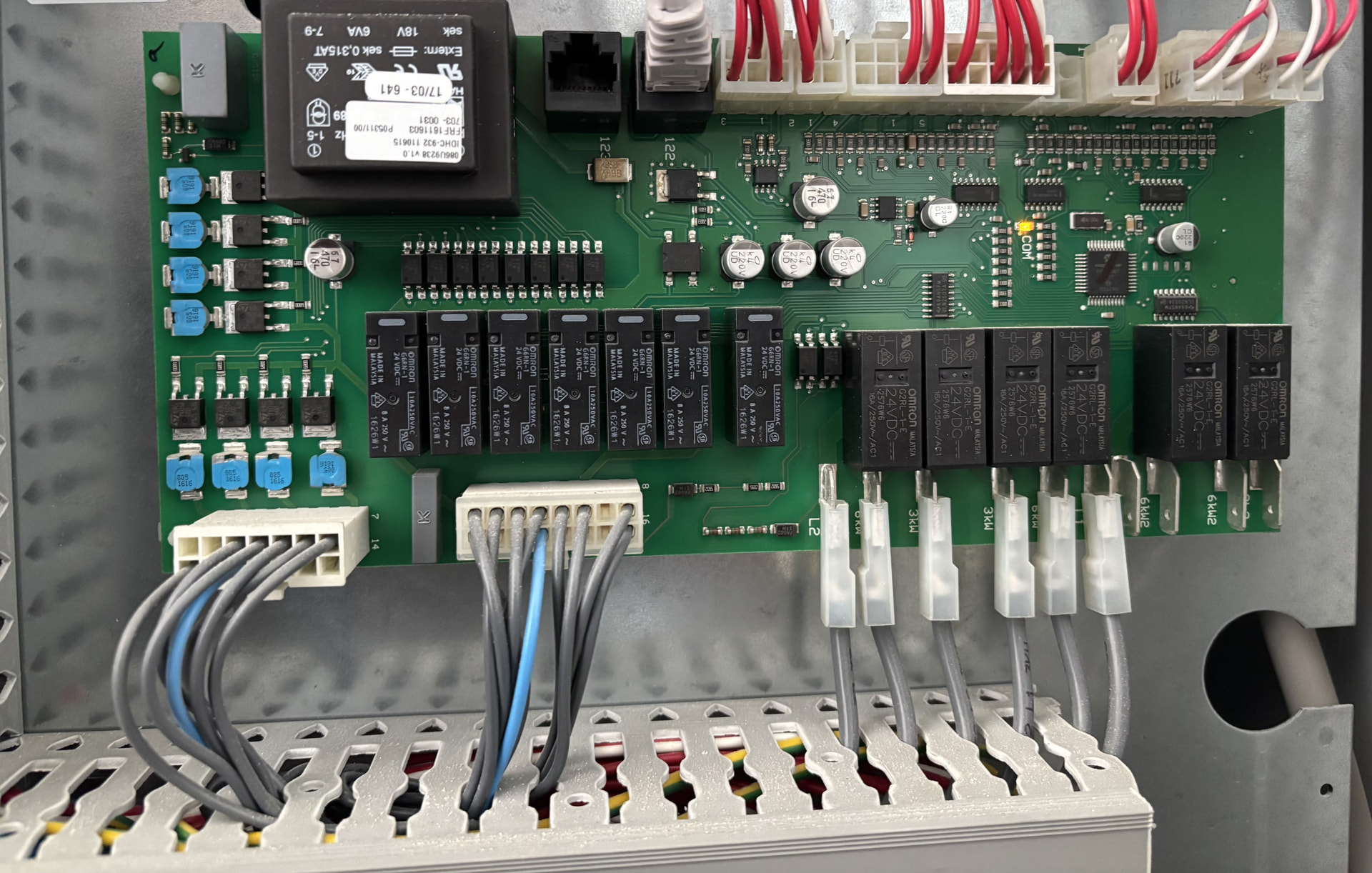
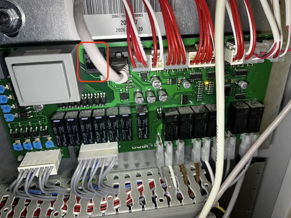
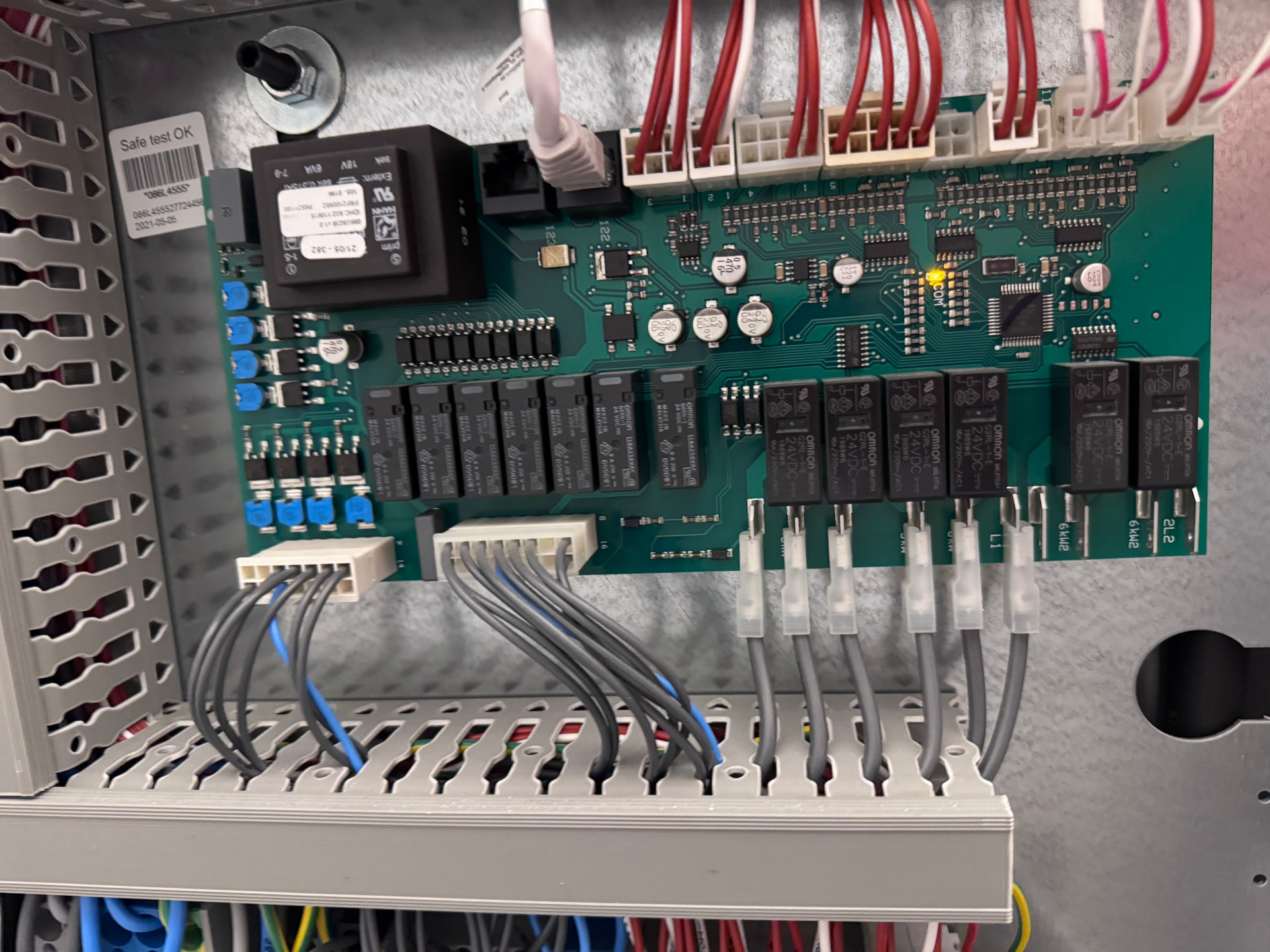
The main controller board in my Thermia has two RJ45 connectors, similar to older Thermia iTec boards with connectors often referred to as 122 / 123.

On my unit, the right-hand connector is used by the display. The left-hand connector appears to be the communication port intended for accessories such as the Thermia Online gateway.

From measurements on the bus, the pin groups appear to be:

RJ45 pins Function
1 + 2 Data line A
3 + 4 Data line B
5 + 6 Bus ground / reference
7 + 8 +12 V

With a logic analyser and a TTL to RS485 converter I managed to start reading and mapping the register.

Now, As final hardware I’m using a Waveshare ESP32-S3-RS485-CAN-U.

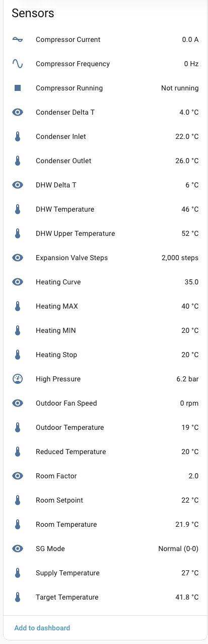
So far I have identified and exposed the following values in Home Assistant:

  • Supply temperature
  • Outdoor temperature
  • DHW temperature
  • DHW upper temperature
  • Room temperature
  • Room setpoint
  • Heating curve
  • Heating min/max
  • Heating stop temperature
  • Reduced temperature
  • Room factor
  • Condenser inlet/outlet temperature
  • Condenser delta-T
  • Compressor frequency
  • Compressor current
  • Compressor running
  • High pressure
  • Target temperature
  • Outdoor fan speed
  • Expansion valve position
  • SG Ready mode

the yaml can be found here : GitHub - ryckema/Thermia_itec: Local Thermia iTec integration with ESPHome / Home Assistant · GitHub

I’m still improving the register mapping and identifying more values, and the next step will be to investigate safe write support for things like the room setpoint and other controls. For now, I’m keeping the integration read-only until the bus timing and arbitration are better understood.

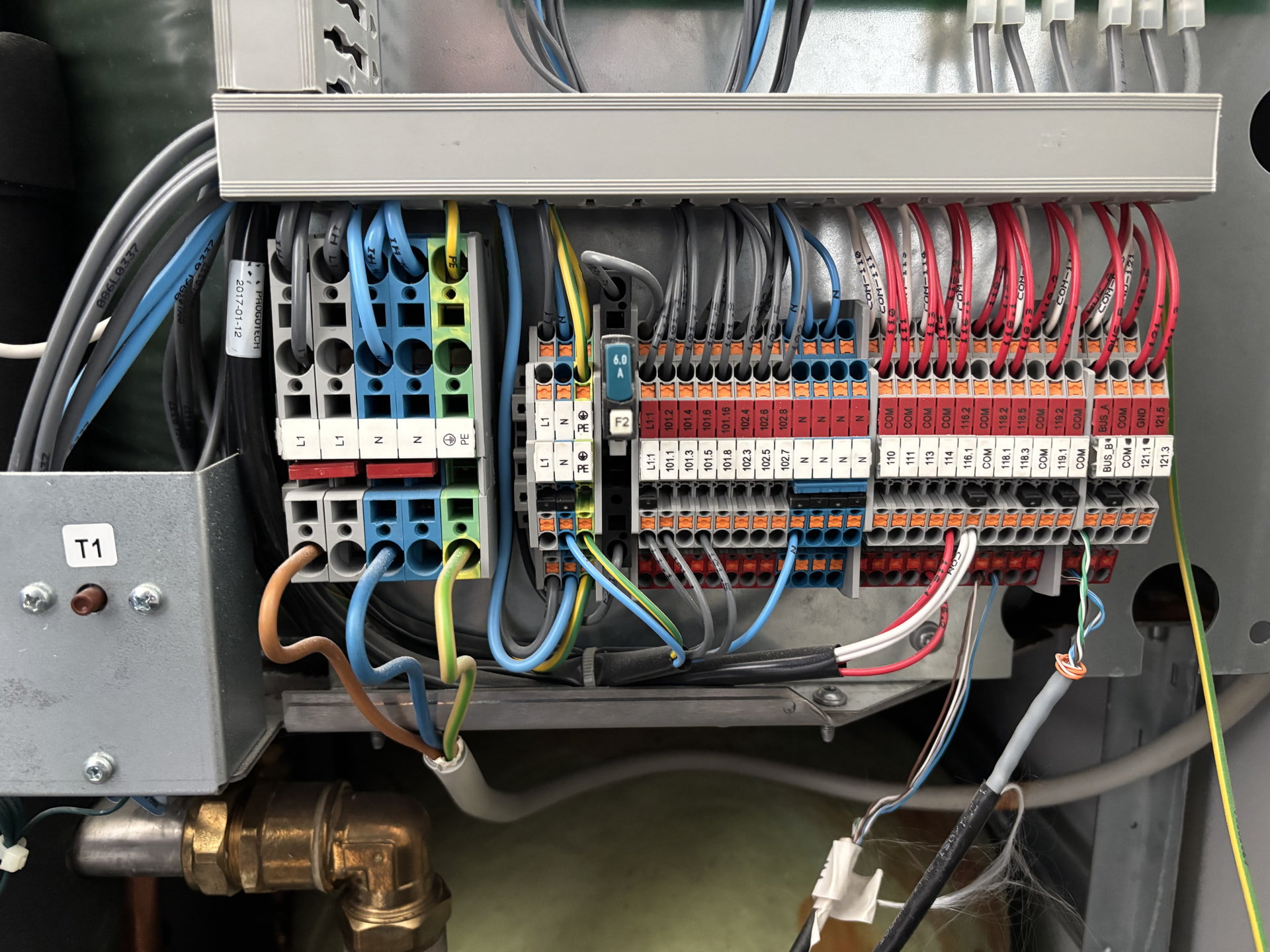
Hi, this looks great and it seems you’ve done exactly what im looking to do. Could you show me how exactly you’ve wired the waveshare up to the board. There isn’t very much online about this. I’ve a danfoss dhp aq HP installed 2017. Attaching photo. Thanks in advance


Hi!
I have the exact same board, you need to connect the waveshare to the empty RJ45 connector on the top left next to the connector going to the display.

I used a RJ47 breakout connector and used connector 1 & 3 (1&2 and 3&4 carry the same signal)
you could use a standard CAT5 cable, but you’ll need to find the correct pairs ( there is 2x2 signal cables , 2 ground, 2 12v)

I’m the iTec Eco 8 owner ryckema has been comparing notes with on varmepumpsforum. Posting the cross-check
here as well, since a second unit either corroborates a map or it doesn’t, and that seems worth having in the
thread rather than in a Swedish forum only.

Mine is a 2017-era iTec Eco 8 on the Danfoss DHP-AQ board, so a different model from ryckema’s XTR M on the
same platform. Anything that matches across the two is more likely to be a platform property than a per-unit
accident. One practical note for reading both maps side by side: his addresses are hex, mine are decimal and
they are the same numbers — B3B0 is 46000, B3C5 is 46021, A80F is 43023, 03F4 is 1012. What his config calls
“FC17” is function code 0x17, i.e. FC23 Read/Write Multiple Registers. That cost me a few minutes of confusion.

v26 verified on my unit. My heating season started this week, which handed me a clean A/B: a hot-water
cycle followed by a switch to heating, captured passively.

  • 0x1E FC04 register 0x0014 (operating state) — watched the full run-down 29 → 28 → 24 → 16. The enum
    holds. His v26 note that state 20 is an autonomous sequence and not defrost is the single most useful
    correction for me; I had been planning to hunt defrost there and would have wasted a winter on it.
  • 0x1E FC04 register 0x0015 (status bitfield) — 577 → 65 → 33 → 545 across the handover, decoding exactly
    as his bits: 0x0200 outdoor unit active, 0x0040 hot-water context, 0x0020 heating context. Confirmed in
    both modes, with a clean transition between them.
  • 0x1E FC16 register 0x0004 (mode request) — flipped 2 → 1 at the exact moment the pump moved from hot
    water to heating. I have not seen 3 (cooling) on this unit.
  • 0x02 register A80C — 0 → 65 at hot-water start → 64 when hot water ends and the pump carries on in
    heating, i.e. bit 0 hot-water request. Bit 0 matches what I had from display A/B tests in June, from a
    completely different direction. (Bit 6 is a context bit, not a compressor flag; see the edit note below.)

Two observations, offered so nobody else spends an evening on them.

The 0x1E FC04 block at 0x001E–0x0033 (decimal 30–51) is not a live mirror. It looks like a copy of the
block at 0–21 — register 40 lines up with 10, 50 and 51 with 20 and 21 — and I would not decode it as current
state. It does change, only far more rarely and out of step. On one day register 21 went
577 → 65 → 33 → 545 → 577 → 545 → 577 → 65, while register 51 moved three times, taking the same values
(65, 545, 577) hours later; register 40 behaved the same way and one of its values, 250, matched register
10’s 25.0 C. So it behaves like a delayed or latched copy. I have not measured the lag and will not guess at
the mechanism — treat the pairing as unconfirmed.

0x02 register A80F is not a modulation level. The values match what ryckema reports (5, 10, and a 75–100
band). On my unit it ramps 80 → 100 in steps of 1 over roughly two minutes early in a heating cycle, then
holds 100 for the rest of the run — while compressor frequency sits flat at 38–39 Hz throughout. So it is not
output, load or a percentage. It looks like a counter that saturates.

On transmitting. Both builds here are deliberately receive-only and that is a sensible default, so this is
offered as information rather than a suggestion. TX on this bus turns out to be tractable: I have been
answering the display’s room-sensor poll on accessory slot 0x0A since June, first through an RS485-to-TCP
gateway and now from an ESP32. There is no arbitration problem — the display is the only master, it polls the
accessory slot and waits about 145 ms for a reply, so a slave only has to respect the 3.5-character silence
and answer nothing but its own poll. Reply with 0A 17 06 <room temp x10> 00 00 00 00 CRC and the display
auto-detects a room sensor and feeds the value into room compensation. Verified in both directions: 18 °C
makes it heat, 28 °C makes it cool. Notes and a one-file passive sniffer, replay included:

That is also why one detail of v26 caught my eye beyond the naming. Documenting B3B1 as a pending
room-sensor setpoint request
explained something I had written off as a bug — an early version of my
emulator echoed the pushed setpoint back into that word by accident. More interestingly it implies a second
control path: a room sensor may be able to request a setpoint change instead of lying about the measured
temperature. Since first posting this I have run that experiment, and it works — details in a follow-up
below.

Still open here, in case anyone recognises them. Slave 0x14 appears on ryckema’s bus; on mine a full
address scan (1–247, FC03 and FC04) finds only 0x02 and 0x1E plus the polled accessory slots 0x06 and 0x0A.
Register A803 (43011) reads a steady 36 on my board against his 224/232 with bit 3 carrying SG1 — I have SG
relays to wire in and will A/B that properly, then report back.

And the real gap, unchanged: the online-module slot 0x06. Nothing I feed it activates it, and the address
scan says there is no hidden slave, so the module must speak through those twelve registers in a format nobody
has. The old Danfoss Link HP-kit (086L2382 / DCM03) drove these pumps locally without any cloud, so this is
not cloud-gated by design. If anyone here owns a Thermia Connect, Thermia Online or Danfoss DCM module, sixty
seconds of bus traffic with it plugged in is the one capture that would unlock this for everyone.


Edit: the paragraph about the 30–51 block originally said it is “frozen, a snapshot taken at init”, on the
grounds that it had not moved all day. That was wrong — the block does move, just rarely and out of step. The
error came from querying a full day of history in the morning, before the day was over, and reading a single
unchanged value as “never moved”. Flagging the edit rather than quietly rewriting, in case anyone read the
original.

Edit: the A80C bullet originally read “bit 6 compressor”. That was wrong too. Bit 6 stays set through
compressor stops and through heating-stop with the compressor at 0 Hz, so it is a context bit, which is how
ryckema’s list already treats 64. Details in a later post.

Thanks, this is very useful — especially having the same fields confirmed on an Eco 8 / DHP-AQ board.

A few things have moved on here since v26.

On A80F I agree with the main conclusion: it is definitely not compressor modulation/load. On my XTR M I have seen 5 → 10 after cold boot, but also 80 → 50 → 80 in passive captures, so I would probably describe it as some kind of sequencing/control value rather than a simple counter.

The biggest update is the 0x06 Online/DCM slot. I now have a repeatable transport handshake:

  • AFCA=0000: REQ low

  • AFCA=03E8: REQ asserted

  • controller register 0x0F:0861 then goes 0 → 16

  • returning AFCA to 0000 makes 0861 go 16 → 0

So AFCA looks like a transport/data-valid REQ flag. The important part is that this handshake works reliably, but by itself it does not produce a setting change. I have tested a number of payload/layout variants and so far they all ACK correctly without reaching the actual DCM application layer.

Cold boot also gives a reproducible sequence here:

A80E: 0 → 8 → 0x28
A80F/A810: 5 → 10
AFDC: 0 → 0x10

and everything settles within roughly 11 seconds.

If you ever have a passive Eco 8 cold-boot capture, those fields would be a very useful cross-check.

Your B3B1 result also explains one of my earlier observations nicely: a direct master write to B3B1 was ACKed but ignored, while a genuine room-sensor event was accepted. So that path is clearly role/slot-sensitive.

I have also started building a write-capable version of my ESPHome integration. For now I am keeping it tightly guarded and focused on reproducing already-observed protocol behaviour rather than sending arbitrary register writes.

I am still mainly pursuing the 0x06 Online/Connect/DCM03 path rather than room-sensor emulation, because that should ultimately expose the proper control interface.

And yes — a real DCM03 / Thermia Online / Connect startup capture is still probably the single most valuable missing piece.

here some more details on 0x06:

Summary

On the XTR M the display/controller polls slave 0x06 with Modbus function 0x17 / FC23:

slave:       0x06
function:    0x17

read start:  0xAFC8
read count:  0x000C      # 12 words, accessory -> controller

write start: 0xAFDC
write count: 0x0005      # 5 words, controller -> accessory

So the controller supplies:

AFDC AFDD AFDE AFDF AFE0

and expects the accessory to return:

AFC8 AFC9 AFCA AFCB AFCC AFCD AFCE AFCF AFD0 AFD1 AFD2 AFD3

With no slave response, the 0x06 poll interval here is roughly 4.3 s. Any syntactically valid 12-word FC23 response changes polling to an alternating fast cadence of roughly 0.7 s / 1.4 s. That only proves that the controller recognises a transport-level accessory; zero-filled responses do this too, so fast polling is not proof that the Online/DCM application layer has initialized.

The useful part is that one of the twelve response words now has a fairly clear transport meaning:

AFC8  word 0
AFC9  word 1
AFCA  word 2   <-- transaction REQ / data-valid
AFCB  word 3
...
AFD3  word 11

AFCA = 0x03E8 acts as a request/data-valid level. The controller acknowledges it through slave 0x0F, register 0x0861.

The repeatable transaction is:

1. Put payload in AFC8..AFD3, with AFCA = 0000
2. Keep payload stable
3. Set AFCA = 03E8
4. Controller changes 0x0F:0861 from 0000 -> 0010
5. Keep all other payload words unchanged
6. Return AFCA to 0000
7. Controller changes 0861 from 0010 -> 0000
8. Only after that change/clear the payload

Typical measured timing here is approximately:

AFCA assert -> 0861=0010 : ~0.3–0.45 s
AFCA clear  -> 0861=0000 : ~1.0–1.2 s

That handshake is extremely repeatable. We have now generated it dozens of times. The important negative result is that the ACK is transport-level only: the controller will ACK payloads that have no semantic effect. A completed 0861handshake therefore does not mean the DCM command was understood.

One historical envelope that consistently generates the handshake is:

AFC8 = 00FF
AFC9 = 0001
AFCA = 0000 / 03E8 / 0000
AFCB = 0001
AFCC..AFD3 = 0000

I have tested this as a single transaction, persistent state, at cold boot, and as repeated back-to-back transactions. It always gives the expected transport ACK but has not produced a setting change.

I also tested quite a lot of simple interpretations of the other words without finding application semantics:

- AFC8 values including 0000, 0001, 00FE, 00FF, 0100, FFFF
- AFC9 small values / count-like values
- AFCB small values / count-like values
- AFCC..AFD3 individually set to 0001
- several multi-word combinations
- local register numbers such as 03E8/03E9/03F4
- raw Danfoss HE/DHP ParameterIDs
- zero-presence from cold boot
- historical envelope from cold boot
- repeated identical transactions without reset gaps

None produced a semantic setting change. So isolated-word probing is probably mostly exhausted.

Another useful correction: A80E and AFDC are not reliable “DCM logged in” indicators. We have passively observed natural cycles such as:

A80E  0000 -> 0020
AFDC  0000 -> 0020 shortly afterwards
...
A80E  0020 -> 0000
AFDC  0020 -> 0000

even when the ESP was not transmitting. So those changes should not be used as evidence that an emulated DCM session succeeded.

A true cold boot also gave a useful baseline with 0x06 unanswered:

~1.8 s  A80E 0000 -> 0008
~2.8 s  A80E 0008 -> 0028
~5.6 s  AFDC 0000 -> 0010
~11 s   A80F/A810 0005 -> 000A

and then it remained stable. Supplying valid zero responses from the first 0x06 poll changed the polling cadence but did not change that higher-level state. So there are at least three distinct layers:

valid 0x06 response
      ↓
transport presence / fast polling

AFCA=03E8 ↔ 0861=0010
      ↓
transaction REQ/ACK

unknown DCM03 application/session protocol
      ↓
actual parameter read/write

The last layer is still the missing piece.

I also dug into old Danfoss Link CC firmware. At the Link side, DHP parameters use an abstract Set/Get protocol with 16-bit parameter IDs. Relevant examples include:

030A  OperationMode
4400  HeatPumpType
4401  RoomValue
4402  HeatCurve
4403  HeatCurveMin
4404  HeatCurveMax
4405  HeatCurvePlus5
4406  HeatCurveZero
4407  HeatCurveMinus5
4408  HeatStop
4409  RoomFactor
440A  HotWaterStart
440B  ControllerDemand
440C  SupplyLineTemperature
440D  ReturnLineTemperature
440E/440F/4413 ExternalControl
4414  IntegrationMode
4416/4417 EVU

The host-side request format appears to be:

BYTE endpoint
BYTE counts = (GET_count << 4) | SET_count
WORD SET_parameter_ids[]
WORD GET_parameter_ids[]
SET values...

But feeding this format directly into AFC8..AFD3 does not work. The final conversion:

HE/DHP ParameterID + value
      ↓
DCM03 serializer/state machine
      ↓
AFC8..AFD3
      ↓
Thermia controller

appears to live inside the DCM03 itself, not in the Link CC software.

I also have some useful local correlations between the HE parameters and the normal controller settings block:

HE 4402 HeatCurve       <-> 0x0F:03E8
HE 4403 HeatCurveMin    <-> 0x0F:03E9
HE 4404 HeatCurveMax    <-> 0x0F:03EA
HE 4405 HeatCurvePlus5  <-> 0x0F:03EB
HE 4406 HeatCurveZero   <-> 0x0F:03EC
HE 4407 HeatCurveMinus5 <-> 0x0F:03ED
HE 4408 HeatStop        <-> 0x0F:03EE

03F4 is also a room-setpoint mirror, but direct writes to the mirror are not the same as a valid accessory request.

What would be especially useful to cross-check on your Eco 8:

  1. Does any valid 0x06 12-word reply switch your controller from the ~4 s cadence to the same ~0.7/1.4 s cadence?
  2. Does setting response word 2 / AFCA = 0x03E8 make your 0x0F:0861 go 0 -> 16?
  3. If you then return AFCA to zero while holding every other word constant, does 0861 return 16 -> 0?
  4. What are your normal AFDC..AFE0 values during idle/heating/DHW?
  5. Does your controller show the same cold-boot A80E / AFDC sequence?

If those also reproduce on the Eco 8/DHP-AQ, then the whole transport handshake is almost certainly a platform-level DHP-AQ/DCM interface, not something peculiar to the XTR M.

Most valuable of all would still be a passive capture from a real DCM03/Thermia Online module. At this point even one cold boot plus one HeatCurve change would probably reveal much more than another large register scan.

First, a correction you should know about, since you are building a register map from this thread: I
have edited my earlier post here. It said the 0x1E block at 30–51 is frozen, a snapshot taken at
init. That was wrong. It does change — rarely, and out of step with the live block, but it changes.
I had read a single unchanged value in a partial day’s log as “never moved”. If that claim already
went into your map, please drop it. The edit note is on the post itself.

Thanks — the transport handshake is a real step forward, and the Link CC parameter IDs are a nice
independent check on our side: your HE 4402..4408 to 0x0F:03E8..03EE lands exactly on the block we
had named from the service display (curve, min, max, plus5/zero/minus5, heat stop).

Two things from here: the B3B1 result, which I had not run when I wrote the previous post, and your
question 4.

B3B1 works

Since you are now building a write-capable version, this matters: it is a real request channel and
the controller acts on it.
Encoding is x1, so 19 means 19 °C, unlike B3B0 which is x10.

Pump heating, 12 °C outside:

reg1 sent room setpoint
0 (control) 18, unchanged
18 (equals current) 18, unchanged, controller unbothered
19 18 → 19
18 19 → 18
19 again 19, repeatable
0 (release) stays 19

What rules out an echo: every change also appeared in B3C5 — the master’s own push back to the
sensor slot. The controller rebroadcasts the value as its setpoint. Had it ignored B3B1, that word
would have stayed at 18.

Semantics are a physical dial: the controller stores the setpoint, B3B1 is a request to change
it, and 0 means “nothing to request”, not “clear it”. Send once. Restoring a previous value means
requesting it — switching emulation off does not bring it back.

One trap, since you will hit it: make the release step use a value different from the panel’s
current setpoint. My first attempt released at 18 while the panel also said 18, so “latched” and
“reverted to panel” predicted the same result and settled nothing.

This also fits your observation exactly: a master write to B3B1 was acknowledged but ignored, a
genuine sensor event was accepted. Being the accessory is the point, not writing the value.

Effect size caveat: throughout the test the supply setpoint stayed at 25.0 °C and the compressor at
15 Hz, because the supply target sat on the heating-curve minimum and absorbed everything. The
setpoint changes were real; at 12 °C outside they had nowhere to go.

Question 4 — our AFDC..AFE0

Passive log, 2026-09-22, 06:00–13:05 UTC, 781 readings.

AFDD, AFDE, AFDF are a constant 0. AFE0 is the displayed outdoor temperature, x1 — it reads 13
when the panel shows 13 °C.

AFDC is not static here. It pulses 0 ↔ 32 continuously, period about 64 s — 32 held ~17 s, 0 held
~47 s, all day, in every mode, 389 pulses without interruption. You described that move as an
occasional natural cycle; on this board it is a steady heartbeat. That may be the interesting
difference between our units.

AFDC and A80E move together to the second. Rising edges, 09:00–09:06, identical in both:

09:00:19   09:01:25   09:02:27   09:03:33   09:04:33   09:05:40

Two different slaves, so not coincidence — the controller mirrors its own demand word into the push
to the online slot.

This corrects a note of mine, and reinforces your warning. I had the leading push word recorded
as going to 16 on a hot-water demand. It does not survive the data: during a real DHW cycle that
morning, 07:37–08:00, the AFDC rhythm is indistinguishable from every other hour. So AFDC does not
encode a DHW request here either.

Two anomalies, raw and uninterpreted:

  • AFDC read 16 exactly once, at 12:54:57 — and in the same second the outdoor-unit status word
    (0x1E 0x0015) went to 577, i.e. the 0x0200 “unit active” bit came up. One coincidence, not a pattern.
  • A80E carried an extra bit 3 from 12:33 to 12:43 — 8 in the low phase, 40 in the high phase,
    ten minutes, then gone.

Questions 1–3, the handshake

The oracle is already in place here: 0x0861 is decimal 2145, that register is published to Home
Assistant on this side, and it has been a constant 0 for the last two and a half days — the only
gaps are container restarts. So it never moves on its own here, which makes any movement during a
test meaningful. The transmit tooling from the earlier 0x06 work still exists.

That test needs the owner’s agreement before transmitting on a working pump, so no date promised,
but it is first in the queue.

Question 5, cold boot

I would rather not power-cycle the pump just for this. There is a visit to the electrical cabinet
planned anyway — RS485 board and Smart Grid relays — and a passive cold-boot capture costs nothing
once the power is off. I will take A80E, AFDC, A80F and A810 with timestamps from the first poll and
post the result.

Questions 1–3: done, and your handshake reproduces here on the Eco 8. All three answers are yes.

Setup: transmitting through the TCP gateway on the bus rather than an on-bus ESP, answering only the
master’s polls to 0x06, nothing initiated. Payload was twelve zero words, plus AFCA = 0x03E8 in the
“ack” phases. Two full A/B cycles, so nothing rests on a single transition:

Phase Polls Poll interval 0x0F:0861 (observations: values)
silent, 60 s 14 4.26 s 28 × 0
zeros, 120 s 112 0.70 / 1.44 s alternating 56 × 0
AFCA = 03E8, 120 s 113 0.70 / 1.44 s 56 × 16
zeros, 120 s 112 0.70 / 1.44 s 56 × 0
AFCA = 03E8, 120 s 112 0.70 / 1.44 s 56 × 16
zeros, 120 s 113 0.70 / 1.44 s 56 × 0
silent, 90 s 84 still 0.70 / 1.44 s 43 × 0

Q1 — cadence: yes. A plain all-zero reply is enough to move the 0x06 polling from a very steady
4.26 s (10th–90th percentile 4.25–4.26) to your alternating 0.70 / 1.44 s.

Q2 — ACK: yes. 0x0861 went 0 → 16 in both AFCA phases, and every single observation in those
phases was 16; every observation outside them was 0.

Q3 — clear: yes. Dropping AFCA back to 0, everything else unchanged, took the ACK back to 0 both
times.

On timing: first change seen 1.2 s and 0.6 s after setting AFCA, 1.0 s and 0.4 s after clearing it.
Treat those as upper bounds rather than measurements — the controller writes 0x0861 only about every
2 s here, so the resolution is coarse. Consistent with your 0.3–0.45 s and 1.0–1.2 s, but I cannot
confirm the asymmetry.

One thing you did not mention, which may or may not match your unit: the fast cadence outlives the
accessory. After I stopped answering, the master kept polling 0x06 at 0.70 / 1.44 s for roughly two
more minutes, then fell back to 4.25 s on its own — checked passively afterwards. So there is a
presence timeout of about two minutes before the slot is considered empty again.

So the transport layer is common to the platform, not specific to the XTR M. And your caveat holds
exactly as stated: the “ack” payload here was eleven zero words and one flag, which means nothing,
and it was acknowledged just the same. That is transport, not understanding.

Also useful for anyone following: the TCP gateway is fast enough. Every poll in the transmitting
phases got an answer, and the cadence change shows the master accepted them.

AFDC and A80E. During the test AFDC stopped pulsing, and since I had called it a steady heartbeat in my
last post, I did not want to guess whether that was me. It was not.

The heartbeat is the heating-season condition. Checked over eleven days of history (about 1300 ten-minute
bins): AFDC pulses 0 ↔ 32 exactly when the displayed outdoor temperature is below the heating-stop limit — 100 %
of bins at 3 K or more below, 75 % at 2 K, 48 % at 1 K, 0–1 % at or above the limit. That is a hysteresis of
about 2–3 K, and it does not depend on heating being switched on: it pulsed the same way before the heating
season, when the pump was only making hot water. A controlled A/B confirmed it: the owner raised the heating-stop limit from 17 to 20 at 14:04:22 UTC and the first
pulse came 31 s later, with the compressor only starting eleven minutes after that; lowering it back at 14:52:24
stopped the pulsing in the same second. Note that at 14:52:24 the pump also switched to hot water in that same
second, so that transition is not a clean heating-stop on its own; this morning’s natural one at 10:41:30 was.

AFDC 16 is a generic ten-minute window, not a heating-stop signal. I first read it that way, but the history
shows 13 such windows in eleven days, every one lasting 637–646 s, after several different events: entering
heating-stop, starting hot water from heating, during the periodic routine below (3 of its 10 occurrences),
and at other moments I cannot yet attribute.

A periodic routine, 10 out of 10 over eleven days. Once per cycle, A80C enters a state with bits 0x30 set (48
when idle, 112/113 in season) for 62–68 s, and at the exact moment it ends A80E raises bit 3 (values 8/40) for
636–645 s. It happens regardless of whether the compressor is running. The interval is 25 h 33 min, drifting by
about 1.5 h a day.

A possible explanation, offered as a hypothesis only. The mean AFDC pulse period over 7300 periods is 63.87 s.
In those units the routine interval is 1440.1 “minutes”, the 0x30 state is one, and the windows are ten. The
DHP-iQ manual says that during heat stop the circulation pump is exercised for one minute per day. A controller
counting minutes in ~63.9 s would produce exactly this. The routine is predicted for 2026-09-24 around 15:39:36
UTC; I will listen to the pump then and report whether it runs.

0x1E FC04 register 0x0014 is a bitfield, not an enum. Over seven days, sampled every 30 s (about 20 000
samples), each bit matches its signal in 100.0 % of samples: 0x01 compressor running, 0x04 outdoor fan
turning, 0x08 water flow / circulation pump, 0x10 always set. So 16 idle, 24 pump, 28 pump and fan, 29 plus
compressor, and your 20 is the fan alone. For defrost, Samsung reverses the cycle with the fan stopped, so I
expect 25 (0x19) — a value I have never seen yet. Something to look for on the first frosty night.

The request word AFCA, tested further. Thermia Online’s API, in a public debug dump from a DHP-AQ with a DCM
module, addresses parameters by the display’s own register numbers — 1000 heating curve, 1001/1002 curve
min/max, 1006 heat stop, 1090 cooling, plus 1363 operating mode and 1369 link integration. And 0x03E8 is 1000.
So I tested whether AFCA is a register number rather than a flag: 1001, 1002, 999 and 1234 against 1000 as
control at both ends, each A/B with about 28 observations of 0x0861 per phase. Result: ACK only for 0x03E8.
AFCA is a constant, and the 1000 is either a coincidence or a deliberately chosen value. No parameter changed
in any run.

One side effect is consistent, though: while AFCA holds any non-zero value, the AFDC pulse reads 16 instead of
32 (0x03E8 with ACK 3/3, 0x03E9 without ACK 4/4, 32 again in the zero phases). So the controller reads AFCA at
two levels: any non-zero value changes a bit in the heartbeat it sends to the module, and only 0x03E8 produces
the ACK in 0x0F:0861. I had briefly taken the 16 for a NAK; the longer run ruled that out.

One correction of mine, and I have edited post 4 to match: I called bit 6 of A80C “compressor”. It is
not. From 07:34 to 11:15 UTC today it stayed at 64 through three compressor stops, the last one a
heating-stop at 17 °C outside, with the compressor at 0 Hz and the fan at 0. Your “64 = normal” was the
better reading — it is a context bit, not a running flag. Bit 0 as the hot-water request stands.


Edit: extended the same evening, before any reply, with the eleven-day history check, the register 0x0014
bitfield and the AFCA tests. The first version described AFDC 16 as a heating-stop window and missed that the
pump also switched to hot water at 14:52:24.

This is very useful, especially the long-history checks.

A few things from the XTR M side that may help cross-check your findings:

  • Your ~2 minute presence timeout matches what I’ve seen too: once a valid 0x06 responder has established the fast cadence, the controller keeps polling fast for quite a while after the responder disappears before falling back to the slow ~4.3 s cadence.
  • On the XTR M, a plain valid 0x06 presence is not enough to make the DCM/Online accessory appear on the display. I tested this explicitly, including one run where I rebooted the heat pump while the responder was already active. The controller still accepted the responder and used the fast cadence, but nothing DCM/Online-related appeared in the UI. So there seems to be another recognition/session layer above transport presence.
  • Your AFDC/A80E heating-stop finding is particularly interesting because in an overnight passive capture here I saw the same 0x20 pattern very consistently: A80E raises first, and the corresponding AFDC bit follows about 3.7 s later. The high pulse was about 17 s and the cycle roughly 64–65 s.
  • I also did a few cold-boot captures. There is a transient 0x0F FC10 block at 0x04BA..0x04CF during the first few seconds after boot, later replaced by the normal 0x04A6..0x04B2 block. Cooling ON/OFF/ON produced the exact same initial 04BA block, so that block does not directly contain the cooling setting.

I also found the public Thermia Online debug dump from a DHP-AQ/DCM system, and that turned out to be very useful. It exposed a lot of the Online-side register mapping — for example 0x03E8 heating curve, 0x042E Integral A1, 0x0442Activate Cooling, 0x0553 Operation Mode and 0x0559 Link Integration. The particularly useful part is that I could then verify 0x0442 independently on the XTR M bus: changing Activate Cooling on the display really does change the native 0x0F:0442 value. So at least some of those Online register indices map directly onto the local controller address space.

Your 0x1E:0x0014 bitfield mapping is also very helpful. I had already been treating it as a status/bitfield rather than a simple enum, but your week-long correlation gives much stronger semantics for the individual bits.

Right now I’m testing the next layer above presence: whether a fully completed AFCA=03E8 / 0x0861 four-phase handshake is enough to make the controller recognise the accessory at UI level. If that is still negative, it strengthens the idea that the missing piece is identity/binding/application-session logic rather than transport.

Hi guys, I’ve been following your progress over the last week or two on GitHub with interest. I had done some work with chatgpt over the last month and been able to pull similar values from the modbus interface (passive) but held off on going further as was concerned about potential for damaging the HP with any blind writes. I have a spare waveshare rs485 to eth device and got thinking that it might be worth trying to contact one of the contributors of this project - GitHub - klejejs/ha-thermia-heat-pump-integration: Thermia Heat Pump Integration for Home Assistant · GitHub to request they run a capture with your tool. I would be happy to post the waveshare device to them to assist with progress. Ireland would be ideal as it’s where I’m based but could send to anywhere in the EU.

Edit: My unit is a Thermia iTec Total.

1 Like

Three things since my last post, plus answers to yours.

1. The controller output map, from the display’s MANUAL TEST. The owner switched the outputs one at a
time from SERVICE > MANUAL TEST while I logged the bus and the heat pump’s power meter. All times UTC.

Output (MANUAL TEST) On the bus Evidence
REV.V. HOT WATER A80C bit 0 (1) 16:49:14–16:50:17
BY-PASS COOLING A80C bit 1 (2) 17:05:29–17:06:14
POT.FREE A80C bit 2 (4) 16:54:04–16:54:37
EXT.AUX.HEATER A80C bit 3 (8) 16:53:21–16:54:01
IMM. HEAT 1 A80C bit 7 (128) 16:51:45–16:52:29, meter +2.7 kW
IMM. HEAT 2 0x02 register 43021 (A80D) bit 4 (16) 16:52:32–16:53:17, meter +5.2 kW
CONDENSER PUMP (%) A80F follows the setting 17:03:40–17:04:24, 30 → 40 → 50 → 40 → 30, one step per keypress
SYSTEM SHUNT nothing on the bus —

Also: A80C bit 6 (64) drops to 0 when the operating mode is set to Off and returns in AUTO or manual test, so
it is “controller active” rather than any single output. Bit 5 (32) came up together with EXT.AUX.HEATER and
cleared only on leaving manual test — unassigned. Your compound 193 decodes as 128 + 64 + 1: heater stage 1,
controller active, valve on hot water.

A80F is the circulation pump speed in percent. In manual test it tracked the CONDENSER PUMP setting step
for step; below 30 % it went straight to 5, which looks like “pump stopped”. That explains everything we had
seen on it: 10 idle, 80 while a heater runs, and the 80 → 100 ramp at the start of a heating cycle with a flat
compressor frequency, which is the pump spinning up. So not a demand level and not the PID integral.

Two negatives worth having: 0x1E register 0x0002 did not move with either heater stage, so it is not a heater
mode; and the display settings “hot water time” and “heating time” (both 30 min) are not on the bus at all —
changing hot water time 30 → 25 → 30 produced nothing.

2. The controller-minute hypothesis passed its prediction. From eleven days of history I had predicted the
periodic routine for 2026-09-24 15:39:36 UTC. It came at 15:41:33, 117 s later, which is inside the spread of
the earlier intervals (25 h 31 min 55 s to 25 h 34 min 53 s). The A80C 0x30 phase lasted 61.6 s and the
following A80E bit 3 window 640 s. Independently, the night before, the pump alternated between hot water
and heating every 1916–1922 s over eight switches: exactly 30 minutes of ~63.9 s, matching the two 30-minute
settings above, and not 30 real minutes. Whether the routine is the one-minute pump exercise is still open —
nobody was at the pump at 15:41.

3. Your points from the last post.

A80E → AFDC delay: on my frame-timed logs AFDC follows A80E by 0.0–0.2 s while the 0x06 slot is in fast
cadence (26 pairs) and by 0.1–3.7 s in slow cadence (13 pairs). So the controller copies the bit into the next
push to 0x06, and your ~3.7 s is the wait for the next slow poll.

The 0x04BA..0x04CF block: agreed that it is boot-transient. I had it recorded as a constant block, but that
note came from a session full of power cycles; it is not on my bus now.

Online dumps: the Thermia Online integration’s issue tracker has more debug dumps than the ATEC one, including
two from an iTec (display fw 2.4.1, DCM 2.0.17). The low indices match yours and mine (1000–1006, 1008). The
2xxx range differs between models (return temperature is 2001 on the ATEC, 2002 on the iTec), and both
models’ dumps add 2120 PID, 2121 desired supply temperature, 2160–2169 operating times and 2171–2173 defrost count,
time between defrosts and last defrost duration. Integral A1 at 1070 appears in an ATEC dump (fw 3.1.1) as
REG_SER_HEATING_INT, value −59 — I assume that is where yours came from.

On a real gateway capture: an iTec Eco 5 owner with a working Thermia Online gateway contacted me and is
setting up the passive sniffer; the adapter arrives this week. Thanks also to the new poster offering hardware
for exactly this. A second capture from a different model would still be very welcome.

A thermia online log has been posted here : Thermia Online vs lets try a modbus device · klejejs/ha-thermia-heat-pump-integration · Discussion #143 · GitHub
Good hunting :slight_smile:

A note on the two power-up captures from the GH discussion, because the roles of the two files matter for the analysis of the first seconds.

By the capture author’s own description, and by the traffic itself, 090209 looks like a heat pump power-up (the DCM stays powered and answers from the first second), and 090550 like a DCM power-up while the controller keeps running (the DCM starts answering after about 67 s). The C8 FC03 probes (9 in the first 8.5 s) appear only in 090209, which fits a controller boot. Only 090550 shows a silent DCM at the start.

What that gives (one heat pump start, one DCM start):

  • 0xA5 answers from 0.6 s in 090550 while 0x0F stays unanswered until 66.8 s, so A5 is not the DCM. In the same window the controller already polls 0x0F FC03 (start 1800, count 6) and probes A4 (three reads, then one 0x05 FC17) with no DCM answering.
  • In 090209 the controller polls A5 from 1.2 s after its own power-up, and the first FC03 on 1800 follows at 33.2 s, after a complete FC16 state dump (start 1070 up to 1770, 0.4 to 30 s).
  • When the DCM appears in 090550 (first echo at 66.84 s, first mailbox answer at 68.21 s: 0,0,32767,65535,128,7; steady state later 0,0,0,0,1919,6), the controller repeats the whole FC16 dump within 30 s (1000, 1020, 2180, 1040, then 1070 to 1770).

So on that platform the extended A5 and 0x0F FC03 scheduling exists in the controller without any DCM answering, and the DCM only triggers a full state resync when it joins. That points the question of what enables the scheduler at the controller side rather than at the DCM.

Separately, a short confirmation on the Eco 8 (display firmware 2.3.0): a runtime 0x06 responder with only AFD1 set makes the VERSION page show an EXP row equal to AFD1/10 (16, 0, 10, 1 gave 1.6, 0.0, 1.0, 0.1; four values, four matches, COMM.KIT row unchanged), disappearing about 2 min 15 s after the last response.

A small observation on the 03E8 page mapping. On the Eco 8 (display firmware 2.3.0), index 1011 (0x03F3) is the HIGH POWER switch of the normal HEATING menu. Toggled on and off twice (2026-06-19 and 2026-09-26; the last time 0 → 1 at 12:28:45 and 1 → 0 at 12:29:26 local), the FC16 image to 0x0F start 1000 changes only that word. The neighbours 1009=40, 1010=30 and 1013=2 stay put. The numbering is the same as in the status document, because on this unit the values at 1000..1008 and 1012 match the display item for item (curve 30, min 25, max 55, stop 17, setback 18, room factor 2, room setpoint), and the XTR M sample in the status document also has a 0/1 value at that position. The ATEC capture has 60 at index 11, so the meaning of that index may be platform specific, and I would not read it as Curve 2 Max on the iTec units. Also, 1009=40 and 1010=30 are not shown in any Eco 8 menu I could open (normal and service; ZONING is off here), which would fit a second heating curve that only appears with zoning enabled.

New capture, and it is the first one I know of from an iTec (Eco 5) with a genuine Thermia Online gateway; the owner allows sharing the raw log without his name. 10,719 frames, all CRC valid, 1482 s, with an A/B/A power-cycle sequence: pump on with gateway, pump on without gateway, pump on with gateway again.

  1. The gateway is not on 0x06 and not on 0x0A. Every FC17 request to 0x06 (326) and 0x0A (325) goes unanswered for the whole log, 4.2 s cadence. There is no A5, A4 or 05 traffic at all on this iTec, so those addresses look ATEC-specific.

  2. This confirms and extends the 0x0F FC17 071C/0730 exchange already described in the research log as a keepalive/session candidate found without any gateway attached. In this capture it clearly gates the rest of the state machine: the controller keeps sending it every ~4.2 s from power-on, the gateway needs about two boot cycles to answer, roughly two minutes in both cases, and once one valid answer comes back, this exchange stops and the controller starts acknowledging FC16, dumping its full state (1000..1780, then 2000..2160) and polling the FC03 mailbox on 1800. Without the gateway connected (the middle cycle of the three), none of that happens, only the plain 0x0F writes with no acknowledgement, which is exactly what my own Eco 8 does too.

  3. Where our data disagrees with the calendar decoding proposed for this exchange: across the roughly 90 distinct 16-byte values in this capture, spanning two clock hours and using the day of the month that is known from the capture date, none of the eight words match the year/hour/day/minute encoding, including the two words reported as constant. The values look closer to uniform noise, and one exact 16-byte repeat 4 seconds apart looks like a retry of an unanswered exchange rather than a clock tick (a clock would have changed). Two complete pairs are available for anyone who wants to check independently:
    C 63cefb32c6f41382087992370caceeba → R 1691a5f3f8e8d58738924416e8e6a3d5
    C 31fb59fc8fb1175cd89f904d06d92ea4 → R fd636ccd0f921d83ff232a1a2413b372
    These may be the first captured answers on the read side of this exchange. One open guess: the content might depend on whether the unit has ever had an Online subscription or pairing configured, not just on whether a gateway is physically present right now. If anyone can check this on a unit that has genuinely never been paired with Online, that would settle it either way.

  4. The mailbox model already described from the ATEC captures holds on iTec too. A change made in the app sets the second mailbox word, the controller then reads the page from the gateway and applies it: word 1 = 1 leads to a read of 1000 count 14 and index 1012 changes 20 → 30 (and back later); word 1 = 8 leads to a read of 1070 count 15 and 1071 or 1070 goes 1 → 0 (warm water comfort, hot water off). A change made on the display is written by the controller with plain FC16, no mailbox involved.

Raw log and a small timeline script are available on request. Thank you again for the very useful research log, it made sense of this capture much faster than starting from zero.

This is extremely useful — and I think it independently confirms several tracks I had already started converging on from the XTR captures.

A few things line up particularly well:

  • I had already moved away from 0x06 as the actual Online/DCM endpoint after the genuine DCM captures showed the important command path on 0x0F. Your iTec capture now confirms that much more cleanly: 0x06 and 0x0A can remain completely unanswered while the genuine Online gateway still works.
  • I had also promoted the 0x0F FC17 071C/0730 exchange from “odd startup traffic” to a likely service/session gate because it appeared during cold boot/recovery and disappeared from normal runtime. Your A/B/A capture now gives the missing causal evidence: once the gateway gives one valid answer, that exchange stops and the controller enters the full Online state machine.
  • I had reached the conclusion that the controller-owned FC16 pages are primarily state/configuration export, not the actual semantic write ingress. Your observation that display changes are sent with plain FC16, while app changes go through the mailbox and a controller-initiated FC03 read, fits that model extremely well.
  • The 0708 mailbox model from the ATEC captures also seems to transfer to iTec after session establishment. That was one of the big open questions for me: whether the old DCM mailbox was just an ATEC implementation detail or part of the wider iTec/DHP architecture. Your capture strongly points to the latter.

Where your data clearly corrects my earlier interpretation is 071C..0723. I’m going to drop the RTC/calendar interpretation as a general explanation. The ~90 different 16-byte values, the lack of correlation with the actual date/time, and especially the exact repeat after ~4 seconds all fit a retrying challenge much better than a clock payload.

The two 16-byte pairs are therefore probably the most valuable part of the capture for the ESP replacement:

63cefb32c6f41382087992370caceeba
→ 1691a5f3f8e8d58738924416e8e6a3d5

31fb59fc8fb1175cd89f904d06d92ea4
→ fd636ccd0f921d83ff232a1a2413b372

I wouldn’t call it AES/CMAC yet, but my current working model is now much closer to:

controller challenge -> gateway/session response -> Online state unlock

followed by:

0708 mailbox -> controller reads desired page -> gateway returns desired state.

That makes the replacement problem much narrower than it looked a few experiments ago: if I can reproduce the valid 0730 response, the rest of the Online path may already be largely understood.

If you can send the raw log, I’d really like to extract all challenge/response attempts and retries and compare them systematically. In particular, whether repeated challenges always produce the same response, and whether the response survives power cycles unchanged, should tell us a lot about whether this is a deterministic keyed transform, session state, or something tied to pairing/history.

Thanks, and the raw log is already public: it is in the captures folder of my thermia-bus-sniffer repository on GitHub (file itec_eco5_gateway_20260926.log, plain “seconds hex” lines, the same format as the fclauson logs; the capture started at 19:46:31 local time). I can put the small timeline script next to it if that helps.

One correction on my side after reading your EXP248/249: when I wrote that my Eco 8 never shows the 071C/0730 exchange, that was based only on steady-state captures. If the unanswered stream stops by itself after roughly 267 s / 63 requests, steady state is exactly where I would not see it, so for the Eco 8 the question is open until I record a cold start from the first frame.

Timing in the Eco 5 log fits your numbers well. In each of the three power-ups the first challenge came 1.2 s after the bus came back (your +1.283 s). With the gateway attached the answer came at +120.1 s and +119.8 s, after 29 challenges both times, well inside your ~270 s window. In the no-gateway cycle the controller sent 41 unanswered challenges up to +171 s, and then the pump was switched off, so that cycle cannot tell whether the stream would have stopped at ~267 s. The part of the log before the first power-off (pump already running with the gateway connected) has no 071C/0730 traffic at all.

On your two questions, the log is too thin to answer either: there are only two answered challenges, one per gateway power-up, with different challenges, so nothing shows whether a repeated challenge gives the same response or whether the response is stable across power cycles. The one exact repeat (19:58:21 and 19:58:25) was not answered. The owner has been asked for a few more cold starts with the gateway attached, which would add one pair each.

Given your EXP244-246 result (129 of 129 local frames fit your clock encoder exactly), it looks like two regimes rather than one of the two readings being wrong: a clock/service record on your XTR with no endpoint, and noise-like 16-byte values on this Eco 5 with a real gateway (whether it had been paired before is one of the questions I sent to the owner). What switches between them is the interesting part.

That EXP256 result is remarkable: a response taken from a different unit and a different challenge still got your XTR past the gate. Since the missing part now is what the endpoint does after that, here is exactly what the genuine gateway does in the Eco 5 log, in both gateway power-ups (times from the bus coming back):

  1. Response to the FC17 challenge at +120.1 s and +119.8 s, about 70 ms after the request.
  2. From the very next controller frame it ACKs every FC16 block, in this order, each ACK within about 40 ms (a few blocks were acknowledged only on the controller’s retry ~1.4 s later): 03E8/14, 03FC/11, 0410/22, 042E/15, 0442/13, 0456/12, 046A/18, 047E/19, 0492/11, 04BA/22, 04D8/27, 04F6/14, 050A/19, 051E/10, 0532/18, 0546/20, then 055A to 06C5 in 33-register blocks, 06EA/7, 06F1/3, 06F4/19, then 07D0/19, 07E4/17, 07F8/17, 080C/18, 0820/18, 0834/18, 0848/23, 0864/4. So the first block after approval is 03E8/14 and the next one is 03FC/11, not 0410; 0410/22 comes third.
  3. The first 0708/6 mailbox poll came at +158 s and +187 s, in the middle of that chain. The first one in the first power-up was not answered; after that every poll got the idle image 0000 0000 0000 0000 0100 0000, while the FC16 chain continued.
  4. In the first power-up the gateway also ACKed the two passive families 04A6/13 and 085F/5 about 1.4 s before it answered the challenge. In the second power-up those two were ACKed only later, in the middle of the chain. So those ACKs do not look like a precondition.

Later, in steady state, the fifth mailbox word counted down in steps from 988 (0x03DC) through 984, 976, 908, 896, 768 and 512 to 0 within about two minutes. That looks like a set of pending sync items being cleared, but that is my reading, not established.

If you try a next step with ACKs, the Eco 5 sequence suggests: ACK 03E8/14 and every following block, then answer 0708 with the 0100 idle image. The front-panel COMM. ERR ONLINE/LINK in your runs would then be the controller timing out a session that got approved but never serviced. The raw log has all of this frame by frame.

Thanks again — these last two posts have again been extremely useful.

The 03F3 / 1011 = HIGH POWER mapping is a good correction to have. I’ll keep that one model-specific for now rather than carrying over the ATEC interpretation.

More importantly, the Eco 5 Online capture has now moved the work quite a long way.

I have been able to replay one of the captured 0730 responses on my HP. Interestingly, it is accepted even though my local 071C challenge is different. Once that response is sent, the controller immediately enters the same Online state machine seen in the Eco 5 capture.

I have now reproduced the chain locally all the way through:

03E8 -> 03FC -> 0410 -> 042E -> ... -> 06C5 -> 06EA -> 06F1 -> 06F4

with the expected FC16 ACKs, and after that the Thermia starts polling:

FC03 0708 / count 6

So the basic session unlock + state export + mailbox architecture now appears to be shared between the Eco 5 and XTR M.

One thing I initially misunderstood was the 0708 response. I first reused the idle-looking response:

0000 0000 0000 0000 0001 0000

and confirmed that my HP accepts it electrically/protocol-wise, but it just keeps polling 0708 roughly every 4.2 s. I tried three replies and then a 30 s receive-only window; no later FC16 pages appeared.

Going back through the Eco 5 raw logs more carefully, the important clue seems to be that the mailbox response is phase/state dependent, not just an idle keepalive.

In the heat-pump startup capture the first relevant post-sync mailbox reply is:

0000 0000 0000 0000 0080 0006

and shortly afterwards the controller continues with 07D0.

I have now tested that exact phase-matched reply on the XTR as well. The full sync again reached 06F4, the first 0708/6arrived about 1.6 s later, and I replied exactly once with:

0000 0000 0000 0000 0080 0006

The result was interesting but not a full success: 07D0 did not appear. Instead, 0708/6 simply continued polling again at roughly the same 4.2 s cadence.

However, there was a visible state change on the Thermia display after this test: the small lower-right status indicator changed appearance, while the alarm remained active. So the 0080/0006 reply may still be affecting controller state even though it is not sufficient by itself to continue into 07D0.

That narrows the problem again: the missing condition is probably not just “the correct mailbox payload”, but some additional session/controller state that exists in the real Eco 5 Online sequence and that I am not yet reproducing.

Another interesting result is that the same captured 0730 response has worked repeatedly on my iTec despite different local 071C values. It may be some kind of approval/session token, or the controller may validate less of the response than we assumed. I don’t want to overstate that yet, but it is definitely worth investigating.

At this point the architecture still looks roughly like:

071C/0730 session unlock
→ FC16 state sync
→ 0708 mailbox
→ controller reads the requested page

The Eco 5 capture was basically the reference trace we were missing. Thanks again for making it available.

The next steps are now a bit clearer:

  • compare the exact controller/accessory state immediately before the first successful Eco 5 0708 -> 0080/0006 -> 07D0transition against the XTR replay;
  • identify which state or prerequisite is missing locally;
  • once 07D0 is reproduced, continue through the remaining 07D0 -> ... -> 0864/0884 sequence one bounded step at a time;
  • then separate normal mailbox/runtime values from values that actually trigger application actions;
  • finally, test one very low-risk write and verify the controller’s own state changes accordingly.

So at this point I think the transport/session structure is mostly understood. The harder part now is reproducing the exact application/session state around the mailbox and making writes deterministic and safe.

Probably no testing tomorrow, but we’re getting very close.
I’m getting a new icon on the display, first the 0, and in the latest test it was filled (but I also still het the alarm):


Great progress, and the replay result is really interesting. I went back through both raw captures specifically around the 06F4 to 07D0 step, and I think the mailbox reply is not the gate. Three things:

  1. The 0080/0006 reply is not from the Eco 5 log. The capture ending in 090209 that you refer to is the ATEC + DCM recording from the other discussion (it has the A5 03 traffic), not the Eco 5 one. In the Eco 5 log there are 188 polls of 0708 and none of them is answered with 0080/0006; the answers there are the idle 0100 word, the 03DC countdown and a few others. So EXP269 tested an ATEC reply on an iTec-family controller.

  2. 07D0 does not wait for the mailbox. In the first Eco 5 session the gateway ACKs 06F4/19 at 340.474 s and the controller writes 07D0/19 at 340.551 s, before the first 0708 poll even appears (341.855 s, which went unanswered). The 07D0 retry at 342.467 s is ACKed and the chain continues. So 07D0 looks like just the next block in the same FC16 queue.

  3. The common factor in all three real transitions (Eco 5 session 1, Eco 5 session 3, ATEC 090209) is that 085F/5 gets ACKed before the first 07D0:

  • Eco 5 session 3: 06F4 ACK at +182.70 s, then 085F/5 at +183.19 s ACKed, 0708 at +186.81 s, 07D0 at +187.42 s.
  • ATEC 090209: 06F4 ACK at 29.726 s, 085F/5 at 29.778 s ACKed, 0708 at 33.18 s, 07D0 at 33.915 s.
  • Eco 5 session 1: 085F/5 ACKed at +118.7 s, just before the approval response, then 07D0 after 06F4.
  • The run without the gateway: 82 writes of 085F/5, zero ACKs, no session.

085F/5 always carries five zero registers. When it is not ACKed, the controller repeats it about every 2.1 s indefinitely; once it is ACKed, it disappears. 04A6/13 behaves the same way. That is what your EXP268/269 summaries show after 06F4 (21 recurrent 085F/5 frames, counted as background), so on your XTR it looks like it is simply never ACKed.

My earlier point that 04A6/085F ACKs are not a precondition was about getting the approval response accepted, and that still holds. For the step to 07D0, though, it now looks like a precondition. The suggested one-step test: after the 06F4/19 ACK, ACK the next 085F/5 once, exactly like the gateway does, and keep the mailbox as before. Expected result: 085F stops repeating and 07D0/19 follows within a few seconds. It is based on three transitions on two platforms, so it’s a hypothesis, not a proof.

A small note on the idle mailbox frame: your transmitted frame 0F030C0000000000000000010000001C88 is exactly the raw Eco 5 one, so the TX side is correct. The only difference is in how it is written as words: the bytes 01 00 are 0x0100 as a big-endian register, which fits the same word counting down from 0x03DC = 988. This doesn’t change any of your results.

I’m the iTec Eco 5 owner with the online Gateway. You need more cold starts, you will get them. But i do not know how to upload here. Piotrek has a mail.
9:35:00 Start

9:38:00 Off

9:38:10 On

9:42:03 Off

9:42:13 On

9:47:00 Off

9:47:10 On

9:51:00 Off

9:51:00 On

9:55:00 End