I’m working on using a 12V bilge pump as a water pump for a nutrient tank for a hydroponic system I’m putting together. The wiring component is quite simple once you know that in order to turn the pump in one direction, the other direction is also required otherwise the controller does not work (10 hours of life gone) There are 4 signals used for one direction ® and 4 for the other (L) direction (but a pump doesn’t run well backwards). but one only needs 4 in total to get the motor to work.
I used the Arduino library BTS7960 by Christoph Eickhoff to create some sketches for testing with an Uno R3, Nano, and D1Mini. The D1 mini doesn’t work with the BTS7960 library. I even broke down and bought an oscilloscope to find out why. Turned out the library capped the PWM values at 8 bit resolution from 0-255 whereas the D1mini uses 0-1023 and that was the reason PWM values in my sketch would not get the pump to even run.
Obviously, I’d prefer to use the esp for the controller as I also have 3 flow meters attached to the output that will be used to control the pump speed through HA. The pulse sensor is already available with ESPHome but the motor controller is not and I would like some help to create one.
This is what I ended up with for the D1 Mini to function with the BTS7960:
| Function | Pin | Description |
|---|---|---|
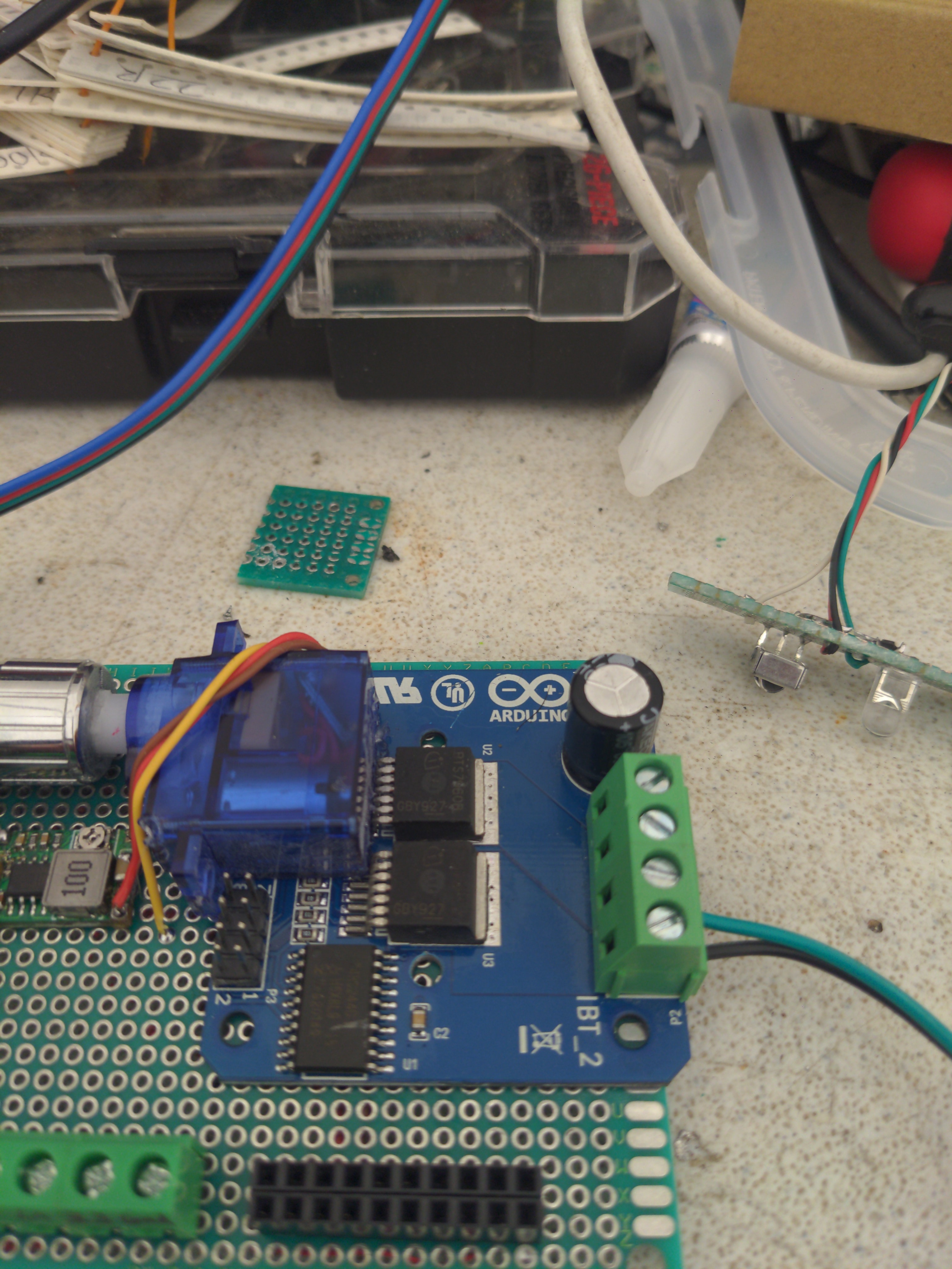
| R_PWM | D6 (GPIO 12) | analogWrite(Pin, Speed) Right Turn PWM input to controller (required) |
| R_EN | D3 (GPIO 0) | digitalWrite(GPIO, HIGH or LOW) H to enable, L to disable (required) |
| R_IS | Not Used | Right turn current warning (Not Used) |
| L_PWM | D4 (GPIO2) | analogWrite(Pin, Speed) Left Turn PWM input to controller (required) |
| L_EN | D5 (GPIO14) | digitalWrite(GPIO, HIGH or LOW) H to enable, L to disable able (required) |
| L_IS | Not Used | Right turn current warning (optional at this time) |
Controller Pin 7 Ground Not Used
Controller Pin 8 VCC (5v) Not Used
If the enable on R is enabled, the the left must be Disabled and speed set to 0. Reverse is true for opposite direction. In my case I don’t need a reverse direction so I didn’t wire it up. Did I say I wasted 10 hours to figure this out??
Arduino Sketch
Arduino Sketch
Modified Library BTS7960.cpp
void BTS7960::setSpeed(int16_t pwm){
  if (pwm < -1023 || pwm > 1023)
  {
    // out of range stop the motor
    stop();
  }else{
    if (pwm < 0 ){
     analogWrite(_LPWM,0);
     analogWrite(_RPWM,-pwm);
    }else{
     analogWrite(_RPWM,0);
     analogWrite(_LPWM,pwm);
    }
  }
}
Having a slider that runs from -100% duty cycle to +100% dudty cycle for the PWM would be ideal. Eventually for this project, I would like to use the flow rates to dynamically adjust the PWM to maintain a constant flow through the system. I have the pieces, I just need help putting them together. It would make life so much easier for using a motor controller.