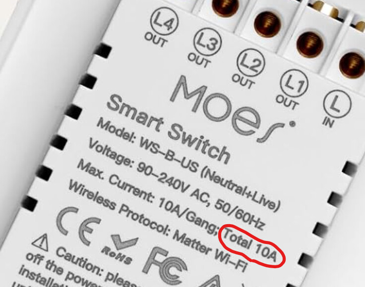
I never said I’d use a run of romex for each of the outbound circuits.
Why do you say “The supply run would have to be 8AWG (10 mm²)!”
For comparison, I have 4 receptacle boxes in my living room each with dual nema 5-15 receptacles. I don’t have to have 2AWG wire and a 120A breaker for that room.
I’m not Happy that the MOES switch uses 10A relays internally. But I found a 10A breaker and ran a circuit just for this.
Through the wall of the basement, I drilled/chiseled a hole to run two ground-contact-rated sealtiight conduits. They go out into the soil (which I excavated a bit for the project) and up through a mulchbed to two outdoor outlets with UL-listed in-use-rated covers. Before i put the dirt back, I packed the hole with hydraulic cement and let that cure. Then I tarred over it on the outside, very thoroughly.
Through each conduit, i pulled 4x THHN 14awg. Two hots and a shared neutral. Gawd home depot thinks its made out of gold not copper these days!
So in the basement there’s a small penetration of the contrete where two conduits end. Over that I’m going to place a metalic 3-gang junction box with two GFCI outlets and this one MOES smart switch.
The 14-2 NM-B runs from a 10A breaker in a breaker panel, through the ceiling/perimeter of the basement, then when it gets to where this junction box it is, I’ll send it down the wall through EMT for physical protection before it gets to the metal jbox.
a 3-gang jbox has plenty enough fill available for 1x nmb and 8x thhn. The NM-B will go to the line lugs of the first GFCI and from that to the line lugs of the second. Thefirst GFCI’s load lugs will feed the MOES and the conduits. The second GFCI is for use in the basement. I do expect whatever is plugged into this outdoors, for years on end, to eventually fault out, and I don’t want that to disrupt my other stuff.
It would be slightly more operationaly resilient to use seperate gfcis for each of the four outputs, but i would feel like a real asshole ordering a 6-gang receptable box. And, becuse the smart switch has individual buttons and leds, if there was a fault you could turn off all loads, reset the gfci, and turn them on one by one until it trips and bingo bango!
I’m plugging in security lights and seasonal holiday lights to these outlets. But I could also very well see myself or someone else using the outlets for a hedge trimmer or power tools. So the smart switch can’t be a dimmer. A heavy duty tool might trip the 10A breaker, but that should prevent it damaging the smart switch.
I should probably put a 10A label on the receps along with the GFCI sticker. But finding a place for it that will be readily visible and also not weather away would be tricky. They should see the “10” on the handle pretty easy when they’re resetting it because the outlet stopped working.
I’ve got 20A outlets right around the corner in the garage and a 15A cord reel in the garage ceiling that SHOULD be used for tools.
These outlets are really intended for lighting, or maybe a security cam. I left a pull string and a cat5 in those conduits too (SHHH don’t tell the codes guy) I might have also left some 1/4" poly along side it for a future solicitor irrigation zone… drilling through concrete is enough of a pain i don’t ever want to feel like I forgot something later.
My earliest idea for this project would have seen four nema 5-15 plugs dangling from grommets in the receptacle box, and bring your own brand of smart outlet controllers to plug them in, or when i move just plug them in direct. That would have looked a bit… busy… and it wouldn’t have had on/off indicators indoors, like the smart switch has. And people get antsy when they see a male connector visible as part of a fixed structure. It was also proving difficult to find pre-moulded 12awg male plugs with pass-through heads at a decent price.pass-through heads would have been important when you want to use just one smart switch but control things on both sides of the mulch bed