a momentary switch (pushbutton) has two states but the “on” state is only a temporary state while the button is being held down. to use that as a toggle the firmware should only use the change from either ‘off’ to ‘on’ (positive edge trigger) or ‘on’ to ‘off’ (negative edge trigger) but it should completely ignore the other. Otherwise as soon as you push the button it would toggle and when you release the button it would toggle back. So, when you push the button the relay switches to the opposite state and when you release the button nothing happens (if you use a positive edge trigger).
a normal light switch has two maintained positions (‘on’ & ‘off’) and can be used in two different modes.
the first mode is the ‘edge detection’ mode in which the firmware looks at ever change in state of the switch (‘on’ to ‘off’ or ‘off’ to ‘on’) and toggles the relay to the opposite state for every change in the switch. so in the end the device doesn’t care what the current state of the switch is compared to the state of the output just that there was change and the output was reversed in response to that change.
the other mode is a ‘follow’ mode in which the state of the output is always the same as the state of the switch (but only when the switch controls the relay but not when HA controls the relay). So if the switch is turned ‘on’ the relay will also turn ‘on’ (unless it was already ‘on’ then nothing would change…I think…I never use that mode). If the relay is ‘on’ and the switch turned to ‘off’ then relay will turn ‘off’ but if the relay is already ‘off’ then nothing happens when you turn the switch to ‘off’.
It’s a Sonoff Basic but you know i’m honestly not sure of the different versions.
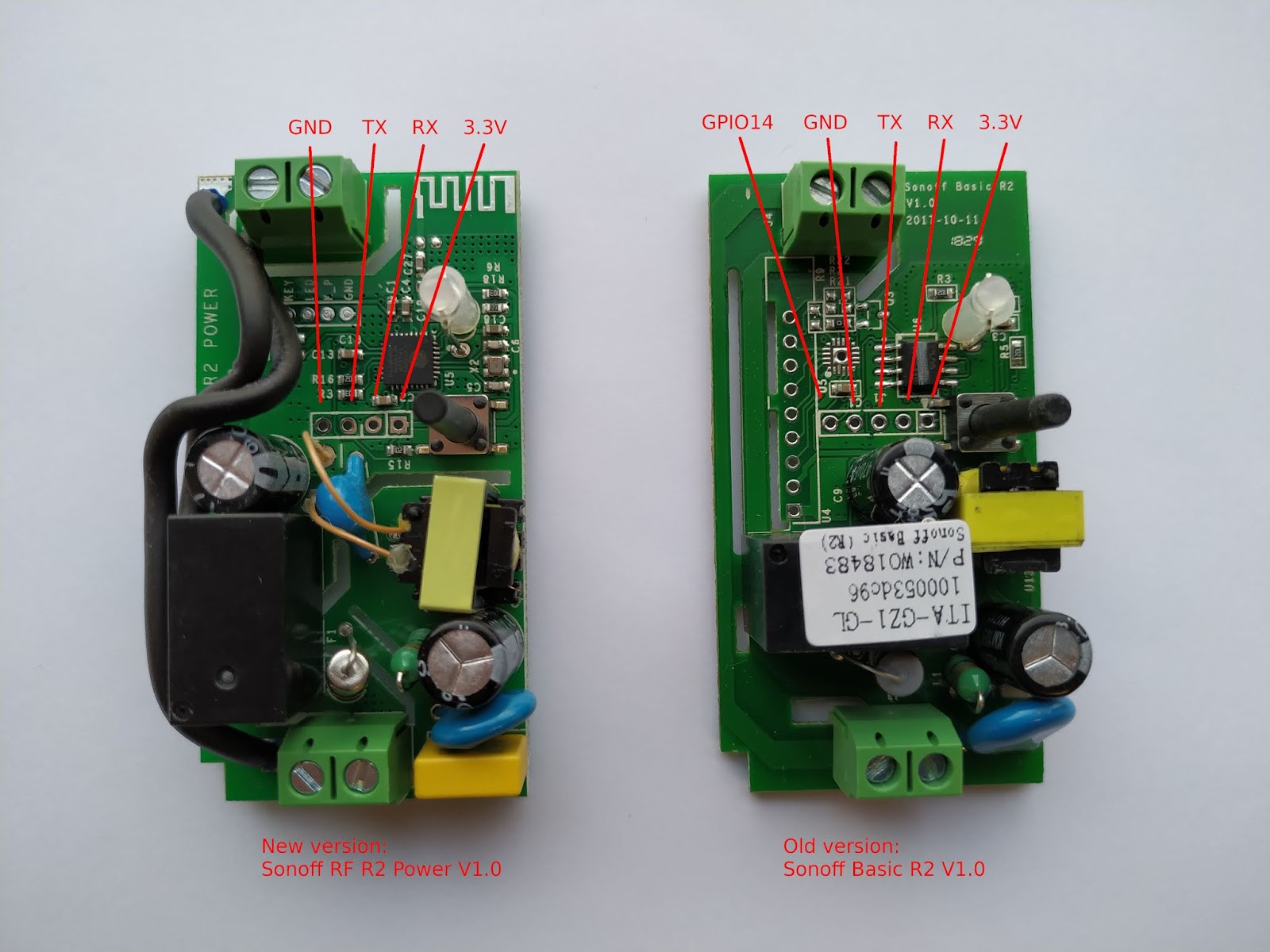
It is the original version with the solder traces before they modified it with the wires. I’ve used a similar set up with the new version too but you need to use a different GPIO since GPIO14 isn’t broken out and accessible any longer. The new GPIO to use is GPIO3 which the Sonoff also uses as the RX pin. But since the only time that RX is active is in program mode that’s not an issue.
I’ll see if I can find a good image of the newer version that I can doctor up to show the connections or I may have to wait till I get home and take a spare one that I have apart to get a good image.
Here is a pic showing the two versions side by side so you can get a good idea of the difterences. It’s literally just connecting one leg of your switch to RX instead of the missing GPIO14.
I can very highly recommend the ESPHome addon for HA for sonoffs.
I have used ESPeasy, tasmota and ESPhome.
They all have pros and cons, but ESPhome is superb!
And I guess for completeness I should add that depending which firmware you flash and/or your end use set up you may have to add a filtering circuit to the switch circuit if you see “ghost” switching.
But I haven’t had any issues with mine since I switched first to Tasmota then on to ESPHome. Prior to that I needed a 10k pull down resistor in the circuit.
Very jealous that you have neutrals at your light switches in the UK! That’s pretty rare!
Means you have loads of choices available to you, shelly (which is personally what I would use) and also things like aeotec nano switch/dimmer as well (zwave). Versternet have some great wiring diagrams like this for a one way circuit (i.e. one switch controlling one light) and this for two way or more (two or more switches controlling one light, like in a hallway). The wiring for the shelly may be pretty similar.
Fair enough! I didn’t read through the whole post, just stumbled across it whilst browsing the forum. I wish I had neutrals at my switches, would give me loads more choice! I can’t be bothered faffing with trying to install a shelly in each ceiling rose.
Not in the UK - typically UK light circuits have a live and a switched live but no neutral. Therfore if you want to install anything that requires a neutral it has to be done in the ceiling rose.
Just my 2 cents: don’t buy Broadlink TC2 they either tend to go crazy, reset their RF code (need to relearn), have sensitivity issues or they fail within a couple of years. Out of 4 switches, all of them have had one or more issues.
Xiaomi Aqara Zigbee seems very good, it will sync the state with HA, solid connection, they look good, very easy to setup; however they only have 1 or 2 gang switches. I digged around the web and apparently people reported these switches failing after a year or two as well.
My guess is that they are compliant.
Xiaomi/Mi has global ambitions and the hub + sensors are starting to be sold in the UK now.
(Although the light switches are not, yet)
I would be surprised if Mi didnt design this kit for the global market (inc compliance) from day one.