Ya… most of them actually are 5v tolerant on the gpio pins though.
You have to keep in mind that that most boards are development boards which consist of 2 parts. They have an esp8266/esp32 IC and that IC is mounted onto a dev board which has its own circuitry and its own spec sheet that will be different than the spec sheet for a plain esp chip.
Up above, i said “most are 5v capable” and people should always check their specific dev board spec sheet to get verification.
For example, all the esp8266 D1 mini’s and esp8266 NodeMCU boards I use, their gpio’s route through a 6v zener diode that clamps it below 6v because, that is the maximum voltage anyone should apply to a gpio without risking damage to the esp IC.
Heres an article that explains it and if you dig around you can even find the back story from several years ago where the Espressif CEO expains why the esp8266 was originally listed as 5v tolerant and the reason they changed it 3.3v and it had something to do with there being no diodes between gpio and 5v rail which was causing a lot of people to accidentally fry their board by making that connection.
They ended up downgraded it to 3.3v so all the people that didnt read the spec sheet which caused them to fry their board and then complain to Espressif or leave bad reviews for online vendors would stop destroying them and also complaining.
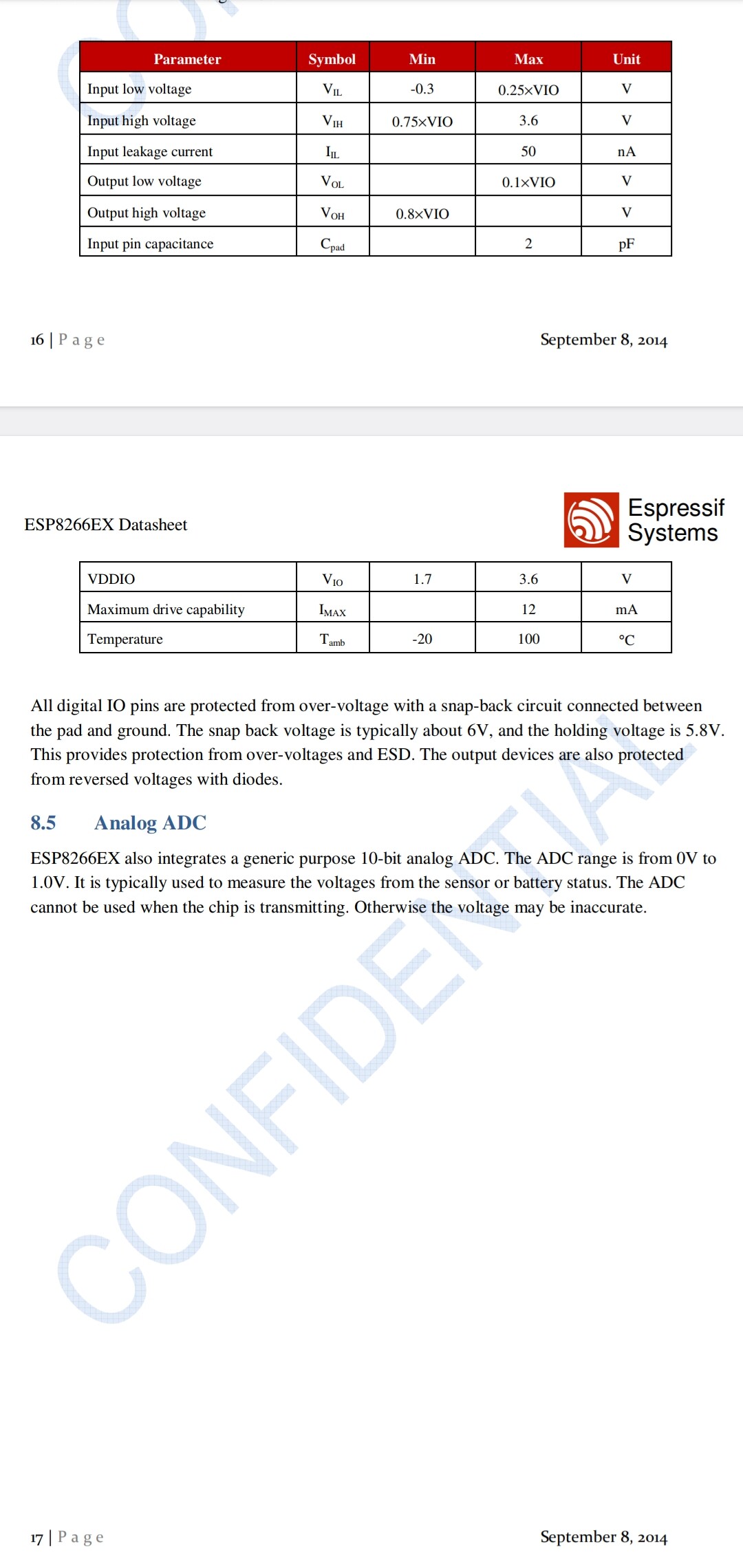
Datasheet gives clearly max 3.6V. But it doesn’t say that brief 5V input makes immediate puff and magic smoke.
Esps are quite robust animals but abusing them probably cause damage over time. Also, one has to be careful when playing with “non compatible” voltage levels. Try to connect Esp gpio to 5V supply and write the pin high…
It’s your board and you can fry (it) if you want to
didn’t want to destroy an ESP8266, so the experiment was conducted with a 1 K series resistor between the curve tracer and the input – which might have biased the results a bit. On the other hand, adding series resistors in front of your inputs is an overall underappreciated practice, 5 V or otherwise.
Put a series resistor in place and you are probably fine. Don’t put a series resistor and you are probably fine until you aren’t (but that might be a long time in the future, or not).
I have only damaged a few esp8266 based boards and they were easy to replace. One was physically damaged when one of my goats decided it would be fun to munch on it. I did manage to fry one years ago by feeding it 5V instead of 3V3, but that took multiple tries.
Except the question was not about the pins being tolerant or not it was about what the pin delivers.
It doesn’t matter what the pin can receive when it’s an output you need.
More than a decade ago I had this issue with a different MCU. The relay board I had was not that good and I had to set the output to be an input to get the relay to work correctly for one of its two states (it didn’t support open drain mode). That is what the solution above does, but there is the concern about 5V tolerance of the pin in input/hiZ/open collector mode.
Still out of specs. But probably the safest “grey zone state” seen on this forum.
Current through gpio is less than 50 nanoamps according to datasheet.
Data sheet for what? As i explained already, there are 2 data sheets. 1 for an esp alone and another spec sheet for dev boards. 95% of the time people are looking at the wrong spec sheet.
I also explained that you can find the post put out by Espressif that explains why they downloaded the esp8266 to 3.3v and it used to be listed at 5v.
I have many boards that have 5v sensors wired to gpios as inputs, some of them have been going nearly 3 years and i assure you, they have no issues handling it or experience damage over time.
Esp has never been rated tolerant to 5V on documentation.
And believe me they would do if they could.
That would make more money, there are not many 3.3V MCUs that are rated for 5V inputs…
I have as well. And others that got fried.
I have serial connections between 3.3V and 5V devices, I have cooling fans without flyback diodes, IR-LEDs driven 10x rated current etc.
Just my choice. But wouldn’t do it on a circuit that has to be reliable, where failure could be painful or on setup I give to someone else.
They certainly were rated for 5v initially and you can surely go find the backstory online, its still floating on the web.
Here is the Espressif CEO CONFIRMING the gpio pins are 5v tolerant as i’ve repeatedly said now at least 5 times. Im citing sources and facts, yet you cite nothing but your opinion. At this point, if you still cant get it through your hard head then you can just disagree and keep believing things based on online comments i guess.
A cancelled post on facebook doesn’t make the rating.
On datasheet it has never been above 3.6V
And I repeat 5times, Espressif would rete the pins 5V tolerant if they could because it would give them economical advantage. But they just can’t.
the datasheet clearly states a maximum voltage of 3.6V
You are free to exceed what the datasheet says, just don’t expect any help/sympathy if/when there is a problem.
Just because you haven’t experienced any issues running with scissors doesn’t mean everyone should be doing it. Or, just because many people have not had any issues jumping off cliffs means it is a safe and effective thing to do.
I personally have damaged at least one esp8266 with over voltage, so I am much more careful now.
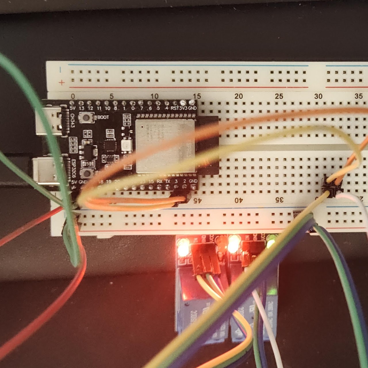
This code solved the issue I was having with my 1 channel relay. It would not turn off. No matter what and I could not figure out the problem. The 2 channel relay was not having the same problem.
Actually, the 2 lines that made the difference were: