did you connect it to a separate D1 Mini and integrate back into HA?
If so how did you do it?
did you connect it to a separate D1 Mini and integrate back into HA?
If so how did you do it?
I have an ML201136 (Blue board) with four SCT013 clamps and an ESP8266 (Wemos D1 Pro), but I’m not having any luck setting it up to show anything.
I am still learning about how to do all this, so apologies in advance for the beginner questions. I’ve emailed Mottram Labs, but they pointed at this post, with no further explanation. It could be that you need to have a lot of advanced experience to do this, but it looked like it should be relatively easy;
What I ‘think’ should work, is to use Tasmotizer to flash my D1 Pro with ‘tasmota-sensors’, then install it on the board, and assign GPIO inputs to relevant sensors, if that works, I would expect to see four sensors in the Tasmota home page with a value.
I’ve got as far as seeing the Tasmota home page, but can’t find any documentation stating which sensors to assign to which GPIO slots, which makes me think I’m not doing it correctly.
Can I even do it this way, or am I barking up the wrong tree?
I’ve had a look at running the yaml from here: Mottramlabs 4CH CT Sensor ESPHome YAML - Pastebin.com by calling it from the configuration.yaml, but it complains about the ‘state: !lambda’ line, among other things, so I’ve shelved that for now.
I’ve been avoiding pursuing this for a very long time, because I knew it’d be a headache. If I can get this working, I’ll assemble documentation for mortals and post it to Git.
Thanks in advance for any help.
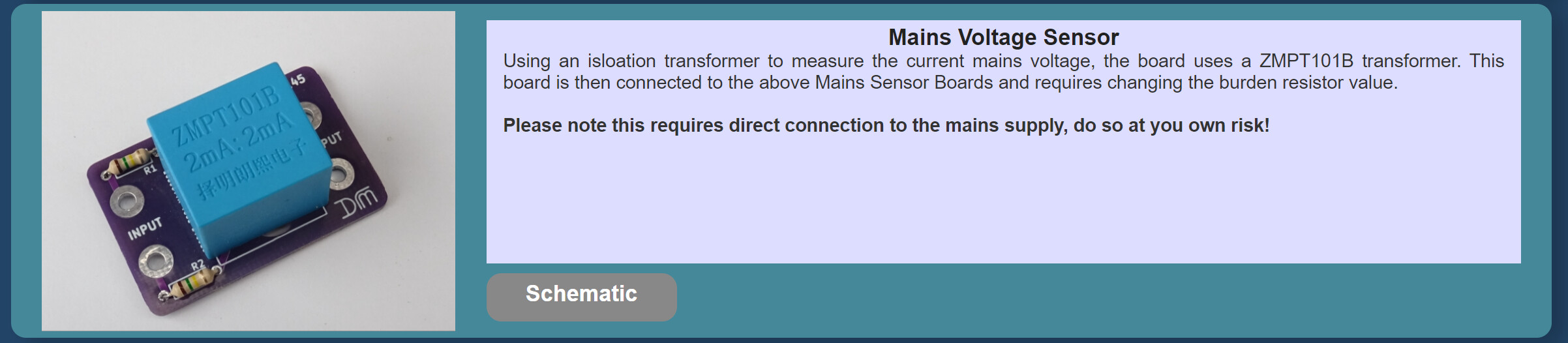
Yes, I have a ZMPT101B connected straight to a D1 Mini and just used ESPHome config to get it working! Happy to share the code when youve got it connected!
Sorry for the late reply!
I use the green board, and the ESPHome Yaml you posted is for this. I think from memory the biggest difference is the green board uses ADS1115 where-as the blue didnt have this capability. So I would guess this needs removing from the YAML as its looking for ADS1115
Thanks for that, I’ve set it up on ESPHome, after a bit of faffing, and am now the proud owner of an ESPHome ‘device’, and the little orange RUN light on the blue board has lit up, although the sensors currently show ‘unavailable’.
This is where my ESPHome knowledge runs out however… I’m able to add the yaml to my default configuration.yaml page, but come unstuck when trying to remove all mention of ‘ads1115’, as they seem to be intrinsic in the sensor code. Could there be another sensor type for my board I should be replacing this with?
That board works differently to the one I used. So the YAML will need quite a lot of rework. There is a thread here : ESPHome Support · Issue #1 · Mottramlabs/4-Channel-Mains-Current-Sensor-ESP8266 · GitHub with some extracts.
It used the single onboard analog to digital convertor with an external mux chip to select which CT clamp to monitor. The YAML above cycles through the external CT clamps (using 2 GPIO pins to signal the external mux) and measures each one in turn.
Just like this board you will need to know the current AC voltage in order to accurately convert the measured current to power - either hard coded or read back from HA as I have above.
Hi All.
Im VERY new to HA, Im going to combine HA to my Hubitat automation system. The reason im doing this is for projects like this!
Thank Dean for the post and information, and to all the other contributors.
So im going to do this on my main fuse board. just want to be absolutely certain that im buying the correct components.
I need the Green boards to keep life simple yes? Neither are in stock until next week anyway.
Also has anyone used the voltage sensor advertised by motrom in this project? is there an easier way of getting voltage information?
Thanks
Thanks very much for your assistance on this, I’ve completed my beginner documentation and a .yaml script for the blue board here: GitHub - Mottramlabs/4-Channel-Mains-Current-Sensor-ESP8266: 4 Channel Mains Power Sensor as a pull request (not sure yet if anyone is going to review it).
It shows everything from the components, test lab, ESPHome and HA setup from a beginner perspective. It’s working really well, I need to tweak it to use my voltage in real time, but other than that, it’s spot on.
Edit: I’ve managed to import my voltage from my inverter, but it’s not updating other than once at boot. Is there a way to have it update every 60 seconds?
In my own true style, I’ve asked and managed to answer my own question. Adding these lines allows me to show Voltage in the template, and update it every 60 seconds, after ‘stealing’ the static ID from the ‘substituations:’ part.
#Voltage
  - platform: template
    name: Voltage
    id: voltageupdate
    lambda: return id(ic1Volts).state;
    accuracy_decimals: 1
    unit_of_measurement: V
    update_interval: 60s
I have a fronius inverter which reads voltage placed above the template in the script:
sensor:
  - platform: homeassistant
    name: "Voltage"
    #ESPHome ID
    id: ic1Volts
    entity_id: sensor.fronius_ac_voltage
    internal: true
This appears to be working well.
Are you using the V3 blue board?
If you are can you post your ESP code?
I have a blue V3 board and used the ESP code on the MotrramLabs Github page that was supplied by daveabbott007 and it isn’t working correctly. Only CT1 and CT2 give current values, and they are not correct. CT3 and CT4 give a very low value, even with no current flowing, and it doesn’t change when current is flowing. It isn’t due to faulty current transformers as swapping them between inputs gives the same current values on CT1 and CT2 and no change on CT3 and CT4.
Thanks.
EDIT
I’ve just found your code on the MotrramLabs Github page. I didn’t think to look at the other pull request!
But can you confirm which version blue board you used it on.
Thanks.
EDIT
I’ve got it working. I can confirm that the v3 blue board works correctly with your ESP code.
Are you using ESP Home only? I loaded the yaml but it is not reading anything unfortunately. This is the V3 green board I have.
Hi David, do you have a YAML example for ESPHome for Version 3 green 4 channel board? I can’t get this working with the example provided here. Thanks in advance.
Hi Ben,
Is there any chance you could post your yaml code for the ZMPT101b and D1 Mini integration into HA please?
many thanks,
mel.
Hi All. ive successfully set one of these up (well sort of) can someone give me any idea on the best way to calibrate the CT’s do i set up a couple of known loads connect them and see what they read in HA and adjust accordingly?
I saw a video saying comment out the calibrate liner and the calibrations and then look at the volts in the logs and enter the v val in the log to the matching current in the cal liner section and then un comment them?
Be very grateful if you could tell me how you are doing it.
I used a variety of methods…
On the test bench before install…A couple of test loads (old 40W + 100W light bulb) that I checked with a multimeter and then the clamp but in practice these can be too low to give good accuracy at higher loads.
Then also tested much higher loads (2.5 kw Pool heaterpost deleted by author) and compared to the live readout of my smart meter (need to disable as much of the other loads as possible of course…dont forget to turn the fridge/freezer back on !)
I have bought the NodeMCU version of this power single monitor. All the codes are based on the D1 Mini. Is there any codes for the NodeMCU 8266 board with a single CT Clamp…?
many thanks
Dave
My raw reading was 0.00 when using a 100W ight bulb. I connecting it to my main consumer unit running all the lights in my house and the raw reading moved to 0.02. Naturally, I was just seeing if I could get a reading on the clamp but this is too low for me to use on a test bench. What were your raw readings?