Calibration settings for YF-B10 pulse counter?

Hi All
Has somebody ever managed to calibrate this sensor the right way ?

With the following recomended function on another thread, I get crazy values (500 L when the tap is opened for 2 seconds).

  - lambda: return x * (6 * x - 8);

I found another function based on the manufacturer characteristics ( F = (6 x Q - 8)) but same here, the reading is not accurate.

I can fill 1L in about 15 to 20 seconds with 373 pulses.

Can someone help ?

Thanks !

I don’t have such a flow meter myself, so cannot test this, but as I understand it, in this formula F stands for Frequency in [pulses/second] and Q stands for Flow in [liters/minute].
As you want to determine the flow, with the pulse count as input, you have to change the formula like this:
Q = (F + 8) / 6 with F in [pulses/sec] and Q in [L/min]
However, the ESPHome Pulse Counter Sensor defaults to [pulses/minute], so you need to modify the formula like this (converting for [pulses/sec]):
Q = ((F / 60) + 8) / 6 with F in [pulses/min] and Q in [L/min]
So the pulse_counter filter then should be:

filters:
  - lambda: return (((x / 60) + 8) / 6);

Does that make sense?
If the result is still inaccurate this Github post might be of interest: FY-B10 or YF-B10 flow sensor ESP32 example

1 Like

Hi - I just gave a look and the result seems to be better, closer to the reality.
Will dig into it this evening. Thanks !

So the pulse_counter filter then should be:

filters:
  - lambda: return (((x / 60) + 8) / 6);

Does that make sense?

Ok, so far with a flow meter test with 3L of water, the sensor seems to provide accurate results, so many thanks ! What I don’t know now is how to change the default value (when the tap is closed and X = 0). It returns 1.33 L / min.

Any idea ?

Ah! Of course, I didn’t think of that.
When x = 0 then Q = (((0 / 60) + 8) / 6 = 8 / 6 = 1.333 and that should of course be 0 as well.
It now is in fact a linear function like this, with Q not reaching 0 when x is 0:

YF-B10_filter-1

This type of sensor has a minimum useable flow rate.
One option to solve this issue is to add a step in the function that assures the flow rate to go to zero when the rate is below the minimum useable flow rate. Something like this:

YF-B10_filter-2

While searching the Internet I find several different versions of this YF-B10 sensor with a flow rate range of 2 to 50 L/minute.
So when we assume the minimum useable flow rate to be Q = 2 L/min then the minimum useable pulse rate will be x = 240 pulses/min
So the pulse counter filter can be modified like this to assure the flow rate will go to zero when the pulse count is below 240 pulses/min:

filters:
  - lambda: !lambda |-
      if (x < 240) return (x / 120);
      return (((x / 60) + 8) / 6);
2 Likes

Awesome and brilliant, thanks !! :pray:

312 or 456. :grin:
Pulse counter ESP32 with YF-B10 - I cant calibrate - #17 by Marc77?

hI all. Just to be sure… if the manual says 595 pulse x min
@thusassistint any idea?

If im not wrong.
"filters:

  • lambda: return (x+4)/10/60;

lambda: return (x+4)/10/60;
x= 595
(595+4)/10 = 60 / 60 = 1 Lt…

option with multply

  • platform: pulse_counter
    pin: x
    unit_of_measurement: “l/min”
    name: “Liter per minute”
    filters:
    • multiply: 0.001680672269
      total:
      unit_of_measurement: “l”
      name: “Total no of Liter”
      filters:
      • multiply: 0.001680672269
        option with Lambda

sensor:

  • platform: pulse_counter
    state_class: measurement
    name: “Sensor agua”
    id: flujo_agua_test
    pin:
    number: GPIO15
    mode: INPUT_PULLUP
    update_interval: 1s
    unit_of_measurement: “L/min”
    icon: “mdi:water”
    filters:
    • lambda: return (x+4)/10/60;

Its not very accurate in my case:(

Stream range: 2~50L|MIN$5%

Specification

Model: YF-B10

Interface size: G1

Rated voltage: DC3.5~24V

Inner/Outer Diameter: 24.38mm/32.9mm

Thread length: 13mm

Material: Stainless steel

Water pressure resistance: >1.75MPa

Output pulse high level: >DC4.7V (input voltage DC5V)

Output pulse duty cycle: 50%10%

Insulation resistance: >100M2

Stream range: 2~50L|MIN$5%

Airtightness: close each hole, add 1.7Mpa water pressure test for 1 minute without leakage and deformation Stream pulse characteristics: F=(10*Q-4)÷5%, F is the frequency Q is L/Min, that is, 595 pulses per liter of water

First, please read How to help us help you - or How to ask a good question, and especially the info about formatting code, and edit your post to improve the readability of your Yaml code.

What I understand from your post is that in your case the YF-B10 sensor has the following characteristics:

pulse rate characteristic F = 10 * Q - 4 with a flow range from 2 to 50 L/min at 5%

Here F is the pulse frequency in [pulses/sec] and Q is the flow rate in [L/min]
The 5% probably is the specified accuracy of the sensor.

So this formula calculates the pulse frequency or pulse rate F for a given flow rate Q.
But, similar to what I wrote in my previous post, we want to calculate the flow rate Q from the pulse frequency F, so we can rewrite the formula like this:

F = ( 10 * Q ) - 4 with F in [pulses/sec] and Q in [L/min]
=> F + 4 = 10 * Q
=> 10 * Q = F + 4
=> Q = ( F + 4 ) / 10

However, the ESPHome Pulse Counter Sensor defaults to [pulses/min], so we need to substitute F in [pulses/sec] with x in [pulses/min]
x in [pulses/min] = F * 60 in [pulses/sec] because there are 60 seconds in one minute.

x = F * 60
=> F = x / 60
Q = ( F + 4 ) / 10
=> Q = ( ( x / 60 ) + 4 ) / 10
=> Q = ( x / 600 ) + 0.4

So the filter should be:

filters:
  - lambda: return ( ( x / 600 ) + 0.4 );

However, this linear function again does not go to zero when the pulse count is zero because when x = 0 pulses/min then:

Q = ( 0 / 600 ) + 0.4 = 0.4 L/min

So again like I wrote in my previous post, to correct for this, and knowing that the sensor flow range is only reliable between 2 and 50 L/min, we can modify the filter such that the flow rate Q goes to zero when the value comes below 2 L/min.

We already know that x = F * 60 and that F = ( 10 * Q ) - 4, so:

x = F * 60
=> x = ( ( 10 * Q ) - 4 ) * 60

When Q = 2 L/min then:

x = ( ( 10 * 2 ) - 4 ) * 60 = ( 20 - 4 ) * 60 = 16 * 60 = 960 pulses/min

So when x is smaller than 960 then we want Q to go to zero.
The modified filter then is:

filters:
  - lambda: !lambda |-
      if ( x < 960 ) return ( x / 480 );
      return ( ( x / 600 ) + 0.4 );

The value 480 comes from 960 pulses/min divided by 2 L/min.

Lets now compare this new filter with you current filter.
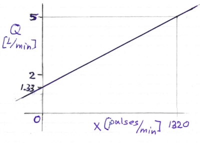
The formula that you are currently using is:
Q = (x+4)/10/60 which in fact is:

Q = ( x + 4 ) / 600

It appears that this linear function is in fact very close to the new function we derived.
This plot shows both filters and how close the results are:

So in the end your current filter is not that far off at all at following the specified flow characteristics.
In fact the resulting value is 0.39 L/min too low for the complete range:
HA_Flowsensorcheck-1_2045

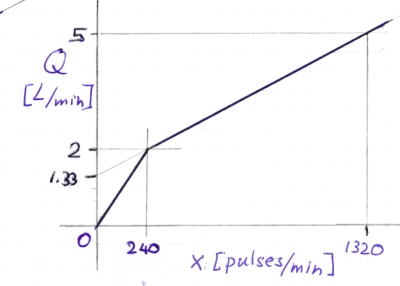
But if we zoom in to the area close to the minimum flow rate of 2 L/min it looks like this:

Here it is visible that the newly derived filter (in green) follows the correct values and goes to zero below 960 pulses/min or 2 L/min.

If your results are way more off then this means that your sensor does not follow its specifications and then it would be best to calibrate your sensor by measuring the true flow rate at several points, meaning measuring the resulting volume at several time intervals for several flow values, and deriving a better filter from these results.

simpleee thanks a lot!!