Does anyone know if there is a native setting on Tuya for this, because I suspect this is it. I prefer not to try and mess with firmware. Specifically, I wonder if there is a way to obtain the Tuya IoT Access ID and Tuya IoT Access Secret? I assume username and password would be from my Nexx account.
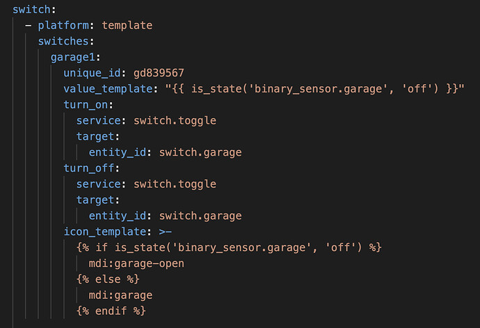
@smoysauce HA and Tasmota have both changed a lot since this was written. Is this the correct way to do the configuration.yaml now?
EDIT: I ended up with this, it’s all working perfectly now:
I also have a “helper” that changes the device type of the switch created above to a “cover”
Glad you got it figured out! I flashed mine with Tasmota and manage it via that rather than MQTT now.
Yeah, it took a lot longer than I thought it would, but I’m happy with the result. My main motivation was the recent security breach at Nexx, they took the device offline for many days. I had been thinking of flashing anyway but this pushed me over the edge.
In the end I have ALL the functionality I had before, icon changing state, shared out to our iOS devices via Homekit, “Siri, open the garage” is working, and it’s much faster now.
Nexx response to the security breach poorly, slowly, and apparently by killing SmartThings compatibility led me to finally tackle this when I got a free moment. Thank you to all of the above contributors for your helpful instructions. I am a novice with soldering but soldering pin-outs on the board was the hardest part! I am posting exactly what I did on Win10, with photos, in case anyone else wants to tackle this.
Tools needed with links to Amazon (these are not affiliate links. I purely want to share):
- Open your NXG-100 case with a thin flat-head screwdriver at the corner. **There MAY be screws that need to be removed first, depending on when you purchased your device. I had a white case with screws and a second black case with no screws.
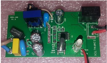
- Identify the pin-outs you need to solder. useful link with a photo which is copied/pasted below
- Solder 4 pin-outs to 3v3, rx, tx, gnd (see photos below for pre-and post-install. Note that for simplicity I soldered all 5 available pin-outs).
- Connect the ribbon cable from the FTDI adapter to the NXG-100 board as follows. It is a good idea to tape or glue them together for ease of disconnecting/reconnecting:
a. 3v3 to VCC
b. Gnd to Gnd
c. Rx to TXD
d. Tx to RXD
e. 1014 on NXG-100 and RTS and CTS on the FTDI adapter are not used. - Install ESPHome-Flasher and the FTDI drivers on windows 10
- Install ESPHome add-on to home assistant
- Start the add-on and open its web-ui
- Hold down the toggle button on the NXG-100 while connecting the FTDI adapter’s USB stick to the PC. Release the toggle once the USB is identified as installed by Windows.
- Click +New Device in the bottom right.
- Give the device a useful name.
- Installation pop-up: Click skip this step, then select ESP8266, then copy the encryption for your safekeeping and press skip. You should now have a new device on your dashboard showing up offline.
- Click to Edit the device on the dashboard to access its YAML file.
- Make the yaml based on the template of Deluxe Config substituting in your device’s name/friendly name, API encryption key, an ota password, and your device’s wifi based on your device’s yaml in the ESPHome dashboard and press save. If you back out of the editor, you can click the 3 dots to select validate to ensure there are no errors in the yaml, and then install via the 3 dots (or install at the top right when you are in the edit yaml box).
- Select manual download > modern format. After two minutes or so, your_device.bin will be downloaded.
- Unplug the USB.
- Open ESPHome Flasher on PC. Select your_device.bin.
- Plug in the USB while holding the reset button down. Do not let go of the reset button.
- Select your serial port on ESPHome-Flasher and click Flash ESP. When it starts installing your firmware, you can release the reset button.
- After flashing is complete, you can disconnect the USB and your device. Plug the NXG-100 into the wall, and confirm it shows up online in the dashboard. The devices should show up as discovered now in your notifications.
- More to come once I confirm these are set up as covers

Before:
After:
Success:
Nice!!! This seems like a far more elegant solution than Tasmota. I had to do all the logic in configuration.yaml, but here it’s all on the device itself. Back when I flashed the Nexx, I was only running Tamota, but I’ve since moved most of my devices over to ESPHome. Let me know if this ends up working ok for you. (tempted to switch this to ESPHome)
Nice and thanks for sharing! I just looked and the deluxe yaml looks like it did everything automatically after all. No scripts were needed and it is super fast. There is a device on my dashboard and I can make it go up and down and it does not go back down if I hit up twice. Seems like it works!
I have a toggle in my Android notification panel that I will need to re-program but I am having trouble removing the old entities from smart things since it is saying they do not have a unique ID number and cannot be removed from UI!
EDIT
Was able to update the names of the entities to my old ones and that allowed the tiles to function without needing any updates. I DO still have the old scripts there but I have not been actively calling them. For reference, this is what I have been using in the past for a script:
main_garage_door:
  sequence:
  - service: cover.toggle
    target:
      entity_id: cover.main_garage_door
    data: {}
  mode: parallel
  max: 10
  alias: Toggle Main Garage Door
  icon: mdi:garage-variant
Awesome! Is the icon changing its state? Showing open when the door is open, closed when it’s closed? That’s what that YAML snippet I have is doing.
Yes, it changes to open when it is open, but when I press down arrow, it shows as closed even though it just stopped opening it. There is a binary sensor called Door Closed which is accurate and can probably, with some of your magic, can do the trick
The script? I have to investigate more but I do not think so
Your solution used a binary switch and one is created when you pull the device into ESPHome. the yaml in ESPHome I used does not appear to have any reference to icon. I wonder if that yaml for the device itself can have a line added to update the icon?
That would be slick, I’m sure it’s possible, but I’m still pretty new to ESPHome myself. I did have to create a few templates from scratch as I couldn’t find any out there, I just stole bits from other templates and used the GPIO info from the Tasmota device repository, which has a lot more devices than the ESPH one.
I have been digging through the yaml and might experiment at some point to make it work but will be hard to do during the work week. It seems like you have more experience with the yaml and programming side of things than I. So let me know if you find a way to make it work first because that would be a fantastic improvement 
OK I made a little progress but could not get it all working right. I read how to do it here. Before I edited out these lines, it made a new second cover which I couldn’t toggle (arg). Both covers had the same icon. I was just picking random icons though so that didn’t help but I think there is a way to use this lambda function to accomplish our goal. I just haven’t figured it out yet. Lambda tells ESPHome the following text is for C++ and not yaml. It is a way to do automation within ESPHome so everything is slick and self-contained. This seems to be the way.


