Connecting the ABL eMH1 EV charger as ESPHome Component

Been looking at communication with my charger.
Found another project that communicated with this charger.
It used ESP S2 Mini so ordered one and it worked out of the box with all of my TTL - RS485 converters.
I decided to try this project on that S2 Mini in case there is something wrong with my ESP32 Wroom but had same issues in S2 Mini.
I happened to look at TTL signals from ESPs with scope and noticed that bit rate seems different with these 2 projects. After some calculations this project seems to push out 115200 baud on both ESPs even though configurations state 38400.

At this point still no idea where things go wrong and how would fix it.

Ok i fixed it by comment out this sensor :wink:

Does someone knows if its possible to get the SOC of the car as an Sensor

Can you share you yaml for this?
Hoping I could find something that would explain my issues.

Hi, sorry for the Late answer. Here is my yaml.


substitutions:
  name: esp-abl-emh1-garage
  device_description: "Monitor and configure ABL eMH1 Charger via RS485/Modbus-ASCII"
  external_components_source: https://github.com/jrv/esphome-abl-emh1
  tx_pin: "GPIO1"
  rx_pin: "GPIO3"
  flow_control_pin: "GPIO12"

esphome:
  name: ${name}
  comment: ${device_description}
  friendly_name: ESP_abl_emh1_Garage
  project:
    name: "jrv.esphome-abl-emh1"
    version: 0.0.1

esp8266:
  board: nodemcu

external_components:
  source:
    type: git
    url: ${external_components_source}
    ref: main
  refresh: 0s

wifi:
  ssid: !secret wifi_ssid
  password: !secret wifi_password

  # Enable fallback hotspot (captive portal) in case wifi connection fails
  ap:
    ssid: "Esp-Abl-Emh1-Garage"
    password: "xxx"

ota:
  - platform: esphome
    password: "xxx"

logger:
  level: DEBUG

# Enable Home Assistant API
api:
  encryption:
    key: "xxx"

uart:
  id: uart_2
  baud_rate: 38400
  tx_pin: ${tx_pin}
  rx_pin: ${rx_pin}
  parity: EVEN

emh1_modbus:
    uart_id: uart_2
    flow_control_pin: ${flow_control_pin}
    id: modbus0

abl_emh1:
  emh1_modbus_id: modbus0
  update_interval: 5s

preferences:
  flash_write_interval: 5min

text_sensor:
  - platform: abl_emh1
    mode:
      name: "Status"
    serial_number:
      name: "Serial number"
      disabled_by_default: true
#  - platform: template
#    name: Chargemode
#    id: chargemode
#    icon: "mdi:car"
#    update_interval: 5s
#    disabled_by_default: true
#    lambda: |-
#      int phaseCnt = 0; 
#      if (id(outlet_state).state == 0xC2) {
#        if (id(l1_current).state > 1.0)
#          phaseCnt++;
#        if (id(l2_current).state > 1.0)
#          phaseCnt++;
#        if (id(l3_current).state > 1.0)
#          phaseCnt++;
#      }
#      std::__cxx11::string result;
#      switch (phaseCnt){
#        case 0: 
#          result = "None";
#          break;
#        case 1:
#          result = "1 Phase";
#          break;
#        default:
#          result = "3 Phase";
#      }
#      return result;

sensor:
  - platform: abl_emh1
    l1_current:
      name: "L1 current"
      state_class: "measurement"
      accuracy_decimals: 0
      id: l1_current
    l2_current:
      name: "L2 current"
      state_class: "measurement"
      accuracy_decimals: 0
      id: l2_current
    l3_current:
      name: "L3 current"
      state_class: "measurement"
      accuracy_decimals: 0
      id: l3_current
    max_current:
      name: "Max current"
      state_class: "measurement"
      id: max_current
      disabled_by_default: true 
      accuracy_decimals: 0
    en1_status:
      name: "EN1 status"
      disabled_by_default: true 
    en2_status:
      name: "EN2 status"
      disabled_by_default: true 
    duty_cycle_reduced:
      name: "Reduced Duty Cycle (max_current)"
      disabled_by_default: true 
    ucp_status:
      name: "Ucp Status <= 10V"
      disabled_by_default: true 
    outlet_state:
      name: "Outlet state"
      disabled_by_default: true
      id: outlet_state
  - platform: uptime
    name: Uptime Sensor
    id: abl_uptime
    update_interval: 15s

number:
  - platform: template
    name: "Max Amps"
    id: set_current
    icon: mdi:arrow-oscillating
    min_value: 3
    max_value: 32
    step: 1
    optimistic: false
    lambda: 'return std::lround(id(max_current).state);'
    update_interval: 1s
    set_action:
      lambda: |-
        ESP_LOGD("main", "Sending modbus value = %d", std::lround(x));
        id(modbus0)->send_current(std::lround(x));

switch:
  - platform: template
    name: "Enable"
    id: enable_switch
    icon: "mdi:power"
    lambda: 'return (id(outlet_state).state != 0xE0);'
    turn_off_action: 
      - lambda: |-
          if ((id(abl_uptime).state > 10.0) && (id(outlet_state).state != NAN)) 
            id(modbus0)->send_enable(0);
    turn_on_action: 
      - lambda: |-
          if ((id(abl_uptime).state > 10.0) && (id(outlet_state).state != NAN))
            id(modbus0)->send_enable(1);

Hello
I have assembled the ESP and the converter everything works for me but I am encountering a problem when stopping charging when there is a lack of energy.
I stop charging by switching the charger to OFF, i.e. the output is off
but when I turn it on again it shows that the vehicle has charging enabled but the car does not start charging I have to turn it on via the app in the car to start charging again.

Tested on both a VW and a Skoda Enyaq
I know that these cars do not have a problem with the same steering settings and using the previous Pulsar Plus wallbox

Do you know where the problem could be?
I also tried not turning off the charging but just reducing the current to 3A but the same problem, the charging then does not start.

It seems to me that the charger stopped supplying the car with an impulse even when reduced to 3A that it is still connected.

I looked that the Ucp Status status is either 0 or 1
Shouldn’t this status change depending on the set Ampere?

Thank you very much for any advice.

Hi together

I’ve made some adjustments to the Home Assistant integration for the Abl Chargers for those who have a RS485 to TCP IP Adapter and don’t want to use a ESP32.

It’s just the one file you have to switch. But I think soon it will be merged into the Main code.

Hi Michael @MagicBugsBunny

I’m genuinely interested in your phase switching automation visible in your screenshot. Would you mind elaborating how you did it physically on the switchboard, what kind of hardware you used and how your automations works? That could probably be quite useful for the community here.

Thanks @DerAutomatiker for the initiative! To what I have tested, it seems it does not work with the latest HA 2025.9.
It probably needs first a bit of rewrite of my code , eventually moving to a coordinator format, as you apparently need some delay. Let us know if you can make it work with the latest HA and feel free to fork and propose a PR on GitHub.

Moin zusammmen,

ich versuche seid geraumer Zeit das Projekt umzusetzten.
AL emh1 mit Rj12 Buchse, ESP32 und RS485
Leider bekomme ich keine Daten.
so sieht es zur Zeit in meiner yaml aus:
ota:

  • platform: esphome

logger:
level: VERY_VERBOSE

uart:
id: uart_2
tx_pin: GPIO${tx_pin}
rx_pin: GPIO${rx_pin}
baud_rate: 38400
data_bits: 8
parity: EVEN
stop_bits: 1
debug:
direction: BOTH # Wichtig: Zeigt uns auch an, was der ESP32 abschickt!
dummy_receiver: true

modbus:

  • id: modbus1
    uart_id: uart_2

    flow_control_pin: GPIO5 ← Testweise auskommentieren, falls dein Adapter automatisch schaltet

modbus_controller:

  • id: abl_controller
    modbus_id: modbus1
    address: 1
    update_interval: 10s

preferences:
flash_write_interval: 5min

sensor:

  • platform: modbus_controller
    modbus_controller_id: abl_controller
    name: “Spannung L1”
    register_type: holding
    address: 0x0040
    value_type: U_WORD
    filters:
    • multiply: 0.1
      unit_of_measurement: “V”

Das bekomme ich als Antwort damit:
[15:22:23.589][VV][modbus:054]: Modbus received Byte 1 (0X1)
[15:22:23.597][VV][modbus:054]: Modbus received Byte 0 (0X0)
[15:22:23.599][VV][modbus:054]: Modbus received Byte 128 (0X80)
[15:22:23.609][VV][modbus:054]: Modbus received Byte 11 (0Xb)
[15:22:23.609][VV][modbus:054]: Modbus received Byte 0 (0X0)
[15:22:23.620][VV][modbus:054]: Modbus received Byte 0 (0X0)
[15:22:23.620][VV][modbus:054]: Modbus received Byte 0 (0X0)
[15:22:23.630][VV][modbus:054]: Modbus received Byte 7 (0X7)
[15:22:23.630][VV][modbus:054]: Modbus received Byte 0 (0X0)
[15:22:23.640][VV][modbus:054]: Modbus received Byte 0 (0X0)
[15:22:23.640][VV][modbus:054]: Modbus received Byte 0 (0X0)
[15:22:23.656][VV][modbus:054]: Modbus received Byte 1 (0X1)
[15:22:23.656][VV][modbus:054]: Modbus received Byte 0 (0X0)
[15:22:23.656][VV][modbus:054]: Modbus received Byte 0 (0X0)
[15:22:23.658][VV][modbus:054]: Modbus received Byte 160 (0Xa0)
[15:22:23.669][VV][modbus:054]: Modbus received Byte 37 (0X25)
[15:22:23.671][VV][modbus:054]: Modbus received Byte 0 (0X0)
[15:22:23.684][D][uart_debug:113]: <<< 00:00:00:00:00:00:00:00:F8:01:00:00:00:00:00:C0:00:00:00:01:00:00:FE:01:00:00:01:00:00:01:00:00:00:00:00:00:00:00:00:01:00:00:01:00:00:00:01:00:00:00:00:00:00:00:FE:00:00:00:02:00:00:00:00:00:00:FF:00:00:00:00:00:00:00:01:00:00:FA:07:00:00:00:00:00:00:00:01:00:00:FE:00:00:00:FD:15:00:00:00:00:00:00:FF:05:00:00:FF:04:00:C0:00:00:00:FF:0B:00:00:FE:00:00:00:00:FE:01:00:00:00:FE:00:00:00:00:00:FF:01:00:80:0B:00:00:00:07:00:00:00:01:00:00:A0:25:00:00
[15:22:23.726][VV][modbus:054]: Modbus received Byte 0 (0X0)
[15:22:23.726][VV][modbus:054]: Modbus received Byte 252 (0Xfc)
[15:22:23.726][VV][modbus:054]: Modbus received Byte 1 (0X1)
[15:22:23.736][VV][modbus:054]: Modbus received Byte 0 (0X0)
[15:22:23.736][VV][modbus:054]: Modbus received Byte 0 (0X0)
[15:22:23.741][VV][modbus:054]: Modbus received Byte 252 (0Xfc)
[15:22:23.760][VV][modbus:054]: Modbus received Byte 1 (0X1)
[15:22:23.760][VV][modbus:054]: Modbus received Byte 0 (0X0)
[15:22:23.762][VV][modbus:054]: Modbus received Byte 128 (0X80)
[15:22:23.763][VV][modbus:054]: Modbus received Byte 5 (0X5)
[15:22:23.771][VV][modbus:054]: Modbus received Byte 0 (0X0)

Hat jemand eine Lösung für mich?

Danke Gruß Jörg

Hi,

I build the component with a WT32-ETH01 and a RS485 to TTL board. My wallbox is a ABL Senec Wallbox 1W22G8. It is working but I have issue with stability and some questions.

The wallbox is a 22kW model but the wallbox is set to 11kW after delivery. When I try to change the max current to 32A it does not change the value. It is only possible to change to lower values. I had to use the ABL configuration tool to set the max current to 32A. I had expected that I could also increase the value through integration. Does the ABL config tool set another register?

Most times changing parameters is working. But sometimes values are not changed. In that cases I had to reboot the ESP to get it agin working. How can I debug this. No errors in the ESP log. I only have A and B connected to RS485, no GND and no resistor. Could that be the reason?

Thanks
Joachim

Hi everyone,

I wanted to share my success story and a hardware recommendation for anyone looking to integrate their ABL eMH1 into Home Assistant using ESPHome.

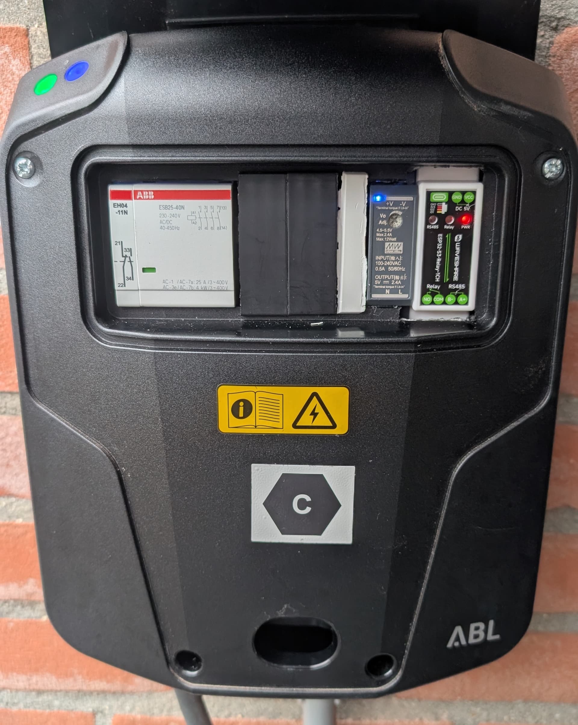
After some tinkering, I successfully installed the Waveshare ESP32-S3-Relay-1CH inside my wallbox. This board is absolutely perfect for this project because it has a built-in SP3485 RS485 transceiver and an onboard relay, making the wiring incredibly clean and simple.

Huge thanks to the creator of the jrv/esphome-abl-emh1 custom component, as the ABL uses Modbus ASCII and this component handles it flawlessly!

Here are some details and tips if you want to replicate this setup:

1. Hardware & Wiring

2. The Onboard Relay as a Watchdog I used the onboard relay (GPIO 47) to switch a red external error LED on my wallbox. I wrote a custom 30-second watchdog script in ESPHome. If the WiFi drops, the HA API disconnects, or the Modbus connection fails for more than 30 seconds, the relay closes and the red LED turns on. It recovers automatically when the connection is restored.

3. Specific Board Settings If you use this specific Waveshare board, keep these settings in mind:

  • The UART pins are: tx_pin: 17, rx_pin: 18.
  • The Flow Control pin for the RS485 chip is 21 (inverted: false).

Here is my complete, stable working YAML configuration. Feel free to use it!

esphome:
  name: abl-emh1
  friendly_name: "ABL eMH1 Wallbox Controller"
  project:
    name: "Waveshare.ESP32-S3-Relay-1CH"
    version: "4.2"

esp32:
  board: esp32-s3-devkitc-1
  framework:
    type: esp-idf
    version: recommended

external_components:
  source:
    type: git
    url: https://github.com/jrv/esphome-abl-emh1
    ref: main
  refresh: 0s

# --- WiFi & Network ---
wifi:
  ssid: !secret wifi_ssid
  password: !secret wifi_password
  # Power save OFF is important for stable Bluetooth Proxy + WiFi
  power_save_mode: NONE
  ap:
    ssid: "ABL eMH1 Wallbox Fallback"
    password: "fallback_password"

debug:
  update_interval: 10s

captive_portal:

# --- API, OTA & Logging ---
api:
  id: api_server 
  encryption:
    key: !secret api_encryption_key

ota:
  - platform: esphome

logger:
  level: DEBUG
  baud_rate: 0
  logs:
    uart: DEBUG
    component: DEBUG

time:
  - platform: homeassistant
    id: homeassistant_time

# --- Global Variables ---
globals:
  - id: error_counter
    type: int
    initial_value: '0'

# --- Bluetooth Proxy ---
esp32_ble_tracker:
  scan_parameters:
    interval: 320ms
    window: 300ms
    active: true

bluetooth_proxy:
  active: true

# --- Switches ---
switch:
  - platform: restart
    name: "Restart Controller"

  # 1. Physical Relay (Red Error Light)
  - platform: gpio
    name: "Error Indicator (Relay)"
    pin: 47
    id: relay_error_light
    internal: true
    restore_mode: ALWAYS_OFF

  # 2. Software Switch (Pause/Start Charging)
  - platform: template
    name: "Enable"
    id: enable_switch
    icon: "mdi:power"
    lambda: 'return (id(outlet_state).state != 0xE0);'
    turn_off_action: 
      - lambda: |-
          if ((id(esp_uptime).state > 10.0) && (id(outlet_state).state != NAN)) 
            id(modbus_hub)->send_enable(0);
    turn_on_action: 
      - lambda: |-
          if ((id(esp_uptime).state > 10.0) && (id(outlet_state).state != NAN))
            id(modbus_hub)->send_enable(1);

# --- Error Monitor Logic ---
interval:
  - interval: 1s
    then:
      - lambda: |-
          bool wifi = network::is_connected();
          bool api = id(api_server).is_connected();
          std::string status = id(abl_status).state;
          
          bool error_detected = false;

          if (!wifi) error_detected = true;        // No Wifi
          if (!api) error_detected = true;         // No Home Assistant connection
          if (status == "Offline") error_detected = true; // ABL Offline
          if (status == "") error_detected = true;        // No data yet
          
          if (error_detected) {
            if (id(error_counter) < 40) {
              id(error_counter) += 1;
            }
          } else {
            id(error_counter) = 0;
          }

          if (id(error_counter) > 30) {
            if (!id(relay_error_light).state) {
              id(relay_error_light).turn_on();
              ESP_LOGW("monitor", "ALARM: System Error > 30s. Relay ON.");
            }
          } else {
            if (id(relay_error_light).state) {
              id(relay_error_light).turn_off();
              // ESP_LOGD("monitor", "System OK. Relay OFF.");
            }
          }

# --- RS485 & Modbus Configuration ---
uart:
  id: abl_uart
  tx_pin: 17
  rx_pin: 18
  baud_rate: 38400
  data_bits: 8
  stop_bits: 1
  parity: EVEN

emh1_modbus:
  id: modbus_hub
  uart_id: abl_uart
  flow_control_pin:
    number: 21
    inverted: false

abl_emh1:
  emh1_modbus_id: modbus_hub
  update_interval: 5s

preferences:
  flash_write_interval: 5min

# --- Sensors ---
sensor:
  # System Diagnostics
  - platform: uptime
    id: esp_uptime
    name: "Uptime"
  
  - platform: wifi_signal
    name: "WiFi Signal"
    update_interval: 60s
  
  - platform: internal_temperature
    name: "Chip Temperature"
    update_interval: 60s
  
  # Debug info
  - platform: debug
    free:
      name: "Free Internal Heap"
      unit_of_measurement: "kB"
      filters:
        - multiply: 0.001
    loop_time:
      name: "Loop Time"
      unit_of_measurement: "ms"
      filters:
        - sliding_window_moving_average:
            window_size: 10
            send_every: 1

  # --- Wallbox Data ---
  - platform: abl_emh1
    l1_current:
      name: "L1 Current"
      state_class: "measurement"
      accuracy_decimals: 0
      id: l1_current
    l2_current:
      name: "L2 Current"
      state_class: "measurement"
      accuracy_decimals: 0
      id: l2_current
    l3_current:
      name: "L3 Current"
      state_class: "measurement"
      accuracy_decimals: 0
      id: l3_current
    max_current:
      name: "Max Current"
      state_class: "measurement"
      id: max_current
      disabled_by_default: true 
      accuracy_decimals: 0
    en1_status:
      name: "EN1 status"
      disabled_by_default: true 
    en2_status:
      name: "EN2 status"
      disabled_by_default: true 
    duty_cycle_reduced:
      name: "Reduced Duty Cycle (max_current)"
      disabled_by_default: true 
    ucp_status:
      name: "Ucp Status <= 10V"
      disabled_by_default: true 
    outlet_state:
      name: "Outlet state"
      disabled_by_default: true
      id: outlet_state

# --- Settings (Sliders) ---
number:
  - platform: template
    name: "Max Current"
    id: set_current
    icon: mdi:arrow-oscillating
    min_value: 3
    max_value: 16
    step: 1
    optimistic: false
    lambda: 'return std::lround(id(max_current).state);'
    update_interval: 10s
    set_action:
      lambda: |-
        ESP_LOGD("main", "Sending modbus value = %d", std::lround(x));
        id(modbus_hub)->send_current(std::lround(x));

# --- Text Sensors ---
text_sensor:
  - platform: version
    name: "ESPHome Version"
  - platform: wifi_info
    ip_address:
      name: "IP Address"
  - platform: abl_emh1
    mode:
      name: "Status"
      id: abl_status
    serial_number:
      name: "Serial number"
      disabled_by_default: true
  - platform: template
    name: Chargemode
    id: chargemode
    icon: "mdi:car"
    update_interval: 5s
    disabled_by_default: true
    lambda: |-
      int phaseCnt = 0; 
      if (id(outlet_state).state == 0xC2) {
        if (id(l1_current).state > 1.0)
          phaseCnt++;
        if (id(l2_current).state > 1.0)
          phaseCnt++;
        if (id(l3_current).state > 1.0)
          phaseCnt++;
      }
      switch (phaseCnt) {
        case 0:
          return {"None"};
        case 1:
          return {"1 Phase"};
        default:
          return {"3 Phase"};
      }

Nice hardware solution!

Hello,

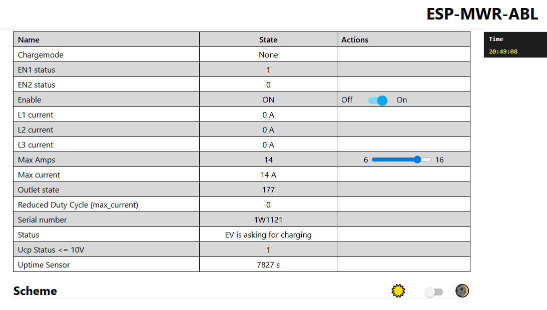
i think my hardware is working. Status EV is aking for charging. Should be B1. But it doesn’t chang to B2 charging.

Any Idea?

You should see the status change in the ESP Log. Try plugging in the car while reading the log file.

First of all, thx for the support.

[14:34:15.467][D][emh1_modbus:123]: Receiving 10 bytes
[14:34:15.467][I][abl_emh1:075]: Status frame received
[14:34:15.467][D][sensor:118]: ‘Outlet state’ >> 161
[14:34:15.468][D][text_sensor:113]: ‘Status’ >> ‘Waiting for EV’
[14:34:15.478][D][sensor:118]: ‘EN1 status’ >> 1
[14:34:15.479][D][sensor:118]: ‘EN2 status’ >> 0
[14:34:15.479][D][sensor:118]: ‘Reduced Duty Cycle (max_current)’ >> 0
[14:34:15.492][D][sensor:118]: ‘Ucp Status <= 10V’ >> 0
[14:34:15.492][D][sensor:118]: ‘L1 current’ >> 0 A
[14:34:15.514][D][sensor:118]: ‘L2 current’ >> 0 A
[14:34:15.514][D][sensor:118]: ‘L3 current’ >> 0 A
[14:34:15.514][D][abl_emh1:106]: Read max current value 0x00 0xB7
[14:34:15.514][D][sensor:118]: ‘Max current’ >> 11 A
[14:34:15.514][D][emh1_modbus:156]: Cleared buffer
[14:34:18.083][D][number:025]: ‘Max Amps’ >> 11.00
[14:34:20.015][D][sensor:118]: ‘Uptime Sensor’ >> 76 s
[14:34:20.444][D][text_sensor:113]: ‘Chargemode’ >> ‘None’
[14:34:20.444][W][emh1_modbus:173]: Query Status Report
[14:34:20.455][D][emh1_modbus:283]: TX → :0103002E0005C9

[14:34:20.467][D][emh1_modbus:123]: Receiving 10 bytes
[14:34:20.467][I][abl_emh1:075]: Status frame received
[14:34:20.468][D][sensor:118]: ‘Outlet state’ >> 177
[14:34:20.479][D][text_sensor:113]: ‘Status’ >> ‘EV is asking for charging’
[14:34:20.479][D][sensor:118]: ‘EN1 status’ >> 1
[14:34:20.491][D][sensor:118]: ‘EN2 status’ >> 0
[14:34:20.491][D][sensor:118]: ‘Reduced Duty Cycle (max_current)’ >> 0
[14:34:20.491][D][sensor:118]: ‘Ucp Status <= 10V’ >> 1
[14:34:20.503][D][sensor:118]: ‘L1 current’ >> 0 A
[14:34:20.503][D][sensor:118]: ‘L2 current’ >> 0 A
[14:34:20.516][D][sensor:118]: ‘L3 current’ >> 0 A
[14:34:20.516][D][abl_emh1:106]: Read max current value 0x00 0xB7
[14:34:20.516][D][sensor:118]: ‘Max current’ >> 11 A
[14:34:20.522][D][emh1_modbus:156]: Cleared buffer
[14:34:25.444][D][text_sensor:113]: ‘Chargemode’ >> ‘None’
[14:34:25.444][W][emh1_modbus:173]: Query Status Report
[14:34:25.456][D][emh1_modbus:283]: TX → :0103002E0005C9

[14:34:25.474][D][emh1_modbus:123]: Receiving 10 bytes
[14:34:25.474][I][abl_emh1:075]: Status frame received
[14:34:25.474][D][sensor:118]: ‘Outlet state’ >> 177
[14:34:25.496][D][text_sensor:113]: ‘Status’ >> ‘EV is asking for charging’
[14:34:25.496][D][sensor:118]: ‘EN1 status’ >> 1
[14:34:25.496][D][sensor:118]: ‘EN2 status’ >> 0
[14:34:25.496][D][sensor:118]: ‘Reduced Duty Cycle (max_current)’ >> 0
[14:34:25.507][D][sensor:118]: ‘Ucp Status <= 10V’ >> 1
[14:34:25.507][D][sensor:118]: ‘L1 current’ >> 0 A
[14:34:25.507][D][sensor:118]: ‘L2 current’ >> 0 A
[14:34:25.518][D][sensor:118]: ‘L3 current’ >> 0 A
[14:34:25.518][D][abl_emh1:106]: Read max current value 0x00 0xB7
[14:34:25.531][D][sensor:118]: ‘Max current’ >> 11 A
[14:34:25.531][D][emh1_modbus:156]: Cleared buffer
[14:34:28.564][D][number:025]: ‘Max Amps’ >> 11.00
[14:34:30.072][D][text_sensor:113]: ‘Chargemode’ >> ‘None’
[14:34:30.472][W][emh1_modbus:173]: Query Status Report
[14:34:30.472][D][emh1_modbus:283]: TX → :0103002E0005C9

[14:34:30.483][D][emh1_modbus:123]: Receiving 10 bytes
[14:34:30.483][I][abl_emh1:075]: Status frame received
[14:34:30.483][D][sensor:118]: ‘Outlet state’ >> 177
[14:34:30.483][D][text_sensor:113]: ‘Status’ >> ‘EV is asking for charging’
[14:34:30.483][D][sensor:118]: ‘EN1 status’ >> 1
[14:34:30.495][D][sensor:118]: ‘EN2 status’ >> 0
[14:34:30.495][D][sensor:118]: ‘Reduced Duty Cycle (max_current)’ >> 0
[14:34:30.495][D][sensor:118]: ‘Ucp Status <= 10V’ >> 1
[14:34:30.508][D][sensor:118]: ‘L1 current’ >> 0 A
[14:34:30.509][D][sensor:118]: ‘L2 current’ >> 0 A
[14:34:30.522][D][sensor:118]: ‘L3 current’ >> 0 A
[14:34:30.522][D][abl_emh1:106]: Read max current value 0x00 0xB7
[14:34:30.522][D][sensor:118]: ‘Max current’ >> 11 A
[14:34:30.527][D][emh1_modbus:156]: Cleared buffer
[14:34:34.807][D][sensor:118]: ‘Uptime Sensor’ >> 91 s
[14:34:35.188][D][text_sensor:113]: ‘Chargemode’ >> ‘None’
[14:34:35.443][W][emh1_modbus:173]: Query Status Report
[14:34:35.443][D][emh1_modbus:283]: TX → :0103002E0005C9

[14:34:35.471][D][emh1_modbus:123]: Receiving 10 bytes
[14:34:35.471][I][abl_emh1:075]: Status frame received
[14:34:35.491][D][sensor:118]: ‘Outlet state’ >> 177
[14:34:35.491][D][text_sensor:113]: ‘Status’ >> ‘EV is asking for charging’
[14:34:35.491][D][sensor:118]: ‘EN1 status’ >> 1
[14:34:35.491][D][sensor:118]: ‘EN2 status’ >> 0
[14:34:35.491][D][sensor:118]: ‘Reduced Duty Cycle (max_current)’ >> 0
[14:34:35.515][D][sensor:118]: ‘Ucp Status <= 10V’ >> 1
[14:34:35.515][D][sensor:118]: ‘L1 current’ >> 0 A
[14:34:35.515][D][sensor:118]: ‘L2 current’ >> 0 A
[14:34:35.522][D][sensor:118]: ‘L3 current’ >> 0 A
[14:34:35.522][D][abl_emh1:106]: Read max current value 0x00 0xB7
[14:34:35.522][D][sensor:118]: ‘Max current’ >> 11 A
[14:34:35.522][D][emh1_modbus:156]: Cleared buffer
[14:34:38.213][D][number:025]: ‘Max Amps’ >> 11.00
[14:34:40.238][D][text_sensor:113]: ‘Chargemode’ >> ‘None’
[14:34:40.444][W][emh1_modbus:173]: Query Status Report
[14:34:40.455][D][emh1_modbus:283]: TX → :0103002E0005C9

[14:34:40.477][D][emh1_modbus:123]: Receiving 10 bytes
[14:34:40.494][I][abl_emh1:075]: Status frame received
[14:34:40.494][D][sensor:118]: ‘Outlet state’ >> 177
[14:34:40.494][D][text_sensor:113]: ‘Status’ >> ‘EV is asking for charging’
[14:34:40.494][D][sensor:118]: ‘EN1 status’ >> 1
[14:34:40.494][D][sensor:118]: ‘EN2 status’ >> 0
[14:34:40.494][D][sensor:118]: ‘Reduced Duty Cycle (max_current)’ >> 0
[14:34:40.507][D][sensor:118]: ‘Ucp Status <= 10V’ >> 1
[14:34:40.507][D][sensor:118]: ‘L1 current’ >> 0 A
[14:34:40.507][D][sensor:118]: ‘L2 current’ >> 0 A
[14:34:40.534][D][sensor:118]: ‘L3 current’ >> 0 A
[14:34:40.535][D][abl_emh1:106]: Read max current value 0x00 0xB7
[14:34:40.550][D][sensor:118]: ‘Max current’ >> 11 A
[14:34:40.550][D][emh1_modbus:156]: Cleared buffer
[14:34:45.263][D][text_sensor:113]: ‘Chargemode’ >> ‘None’
[14:34:45.445][W][emh1_modbus:173]: Query Status Report
[14:34:45.455][D][emh1_modbus:283]: TX → :0103002E0005C9

[14:34:45.471][D][emh1_modbus:123]: Receiving 10 bytes
[14:34:45.471][I][abl_emh1:075]: Status frame received
[14:34:45.471][D][sensor:118]: ‘Outlet state’ >> 177
[14:34:45.482][D][text_sensor:113]: ‘Status’ >> ‘EV is asking for charging’
[14:34:45.482][D][sensor:118]: ‘EN1 status’ >> 1
[14:34:45.493][D][sensor:118]: ‘EN2 status’ >> 0
[14:34:45.493][D][sensor:118]: ‘Reduced Duty Cycle (max_current)’ >> 0
[14:34:45.494][D][sensor:118]: ‘Ucp Status <= 10V’ >> 1
[14:34:45.512][D][sensor:118]: ‘L1 current’ >> 0 A
[14:34:45.512][D][sensor:118]: ‘L2 current’ >> 0 A
[14:34:45.512][D][sensor:118]: ‘L3 current’ >> 0 A
[14:34:45.527][D][abl_emh1:106]: Read max current value 0x00 0xB7
[14:34:45.527][D][sensor:118]: ‘Max current’ >> 11 A
[14:34:45.527][D][emh1_modbus:156]: Cleared buffer
[14:34:48.363][D][number:025]: ‘Max Amps’ >> 11.00
[14:34:49.807][D][sensor:118]: ‘Uptime Sensor’ >> 106 s
[14:34:50.388][D][text_sensor:113]: ‘Chargemode’ >> ‘None’
[14:34:50.444][W][emh1_modbus:173]: Query Status Report
[14:34:50.444][D][emh1_modbus:283]: TX → :0103002E0005C9

[14:34:50.470][D][emh1_modbus:123]: Receiving 10 bytes
[14:34:50.470][I][abl_emh1:075]: Status frame received
[14:34:50.480][D][sensor:118]: ‘Outlet state’ >> 177
[14:34:50.480][D][text_sensor:113]: ‘Status’ >> ‘EV is asking for charging’
[14:34:50.480][D][sensor:118]: ‘EN1 status’ >> 1
[14:34:50.492][D][sensor:118]: ‘EN2 status’ >> 0
[14:34:50.492][D][sensor:118]: ‘Reduced Duty Cycle (max_current)’ >> 0
[14:34:50.504][D][sensor:118]: ‘Ucp Status <= 10V’ >> 1
[14:34:50.504][D][sensor:118]: ‘L1 current’ >> 0 A
[14:34:50.504][D][sensor:118]: ‘L2 current’ >> 0 A
[14:34:50.518][D][sensor:118]: ‘L3 current’ >> 0 A
[14:34:50.518][D][abl_emh1:106]: Read max current value 0x00 0xB7
[14:34:50.518][D][sensor:118]: ‘Max current’ >> 11 A
[14:34:50.524][D][emh1_modbus:156]: Cleared buffer
[14:34:55.446][D][text_sensor:113]: ‘Chargemode’ >> ‘None’
[14:34:55.446][W][emh1_modbus:173]: Query Status Report
[14:34:55.446][D][emh1_modbus:283]: TX → :0103002E0005C9

[14:34:55.466][D][emh1_modbus:123]: Receiving 10 bytes
[14:34:55.466][I][abl_emh1:075]: Status frame received
[14:34:55.479][D][sensor:118]: ‘Outlet state’ >> 177
[14:34:55.480][D][text_sensor:113]: ‘Status’ >> ‘EV is asking for charging’
[14:34:55.480][D][sensor:118]: ‘EN1 status’ >> 1
[14:34:55.501][D][sensor:118]: ‘EN2 status’ >> 0
[14:34:55.501][D][sensor:118]: ‘Reduced Duty Cycle (max_current)’ >> 0
[14:34:55.501][D][sensor:118]: ‘Ucp Status <= 10V’ >> 1
[14:34:55.501][D][sensor:118]: ‘L1 current’ >> 0 A
[14:34:55.501][D][sensor:118]: ‘L2 current’ >> 0 A
[14:34:55.511][D][sensor:118]: ‘L3 current’ >> 0 A
[14:34:55.511][D][abl_emh1:106]: Read max current value 0x00 0xB7
[14:34:55.524][D][sensor:118]: ‘Max current’ >> 11 A
[14:34:55.524][D][emh1_modbus:156]: Cleared buffer
[14:34:58.512][D][number:025]: ‘Max Amps’ >> 11.00
[14:35:00.444][D][text_sensor:113]: ‘Chargemode’ >> ‘None’
[14:35:00.444][W][emh1_modbus:173]: Query Status Report
[14:35:00.456][D][emh1_modbus:283]: TX → :0103002E0005C9

[14:35:00.474][D][emh1_modbus:123]: Receiving 10 bytes
[14:35:00.485][I][abl_emh1:075]: Status frame received
[14:35:00.485][D][sensor:118]: ‘Outlet state’ >> 177
[14:35:00.485][D][text_sensor:113]: ‘Status’ >> ‘EV is asking for charging’
[14:35:00.485][D][sensor:118]: ‘EN1 status’ >> 1
[14:35:00.496][D][sensor:118]: ‘EN2 status’ >> 0
[14:35:00.496][D][sensor:118]: ‘Reduced Duty Cycle (max_current)’ >> 0
[14:35:00.507][D][sensor:118]: ‘Ucp Status <= 10V’ >> 1
[14:35:00.508][D][sensor:118]: ‘L1 current’ >> 0 A
[14:35:00.508][D][sensor:118]: ‘L2 current’ >> 0 A
[14:35:00.522][D][sensor:118]: ‘L3 current’ >> 0 A
[14:35:00.522][D][abl_emh1:106]: Read max current value 0x00 0xB7
[14:35:00.522][D][sensor:118]: ‘Max current’ >> 11 A
[14:35:00.529][D][emh1_modbus:156]: Cleared buffer
[14:35:05.098][D][sensor:118]: ‘Uptime Sensor’ >> 121 s
[14:35:05.098][D][text_sensor:113]: ‘Chargemode’ >> ‘None’
[14:35:05.459][W][emh1_modbus:173]: Query Status Report
[14:35:05.459][D][emh1_modbus:283]: TX → :0103002E0005C9

[14:35:05.478][D][emh1_modbus:123]: Receiving 10 bytes
[14:35:05.478][I][abl_emh1:075]: Status frame received
[14:35:05.479][D][sensor:118]: ‘Outlet state’ >> 177
[14:35:05.479][D][text_sensor:113]: ‘Status’ >> ‘EV is asking for charging’
[14:35:05.485][D][sensor:118]: ‘EN1 status’ >> 1
[14:35:05.485][D][sensor:118]: ‘EN2 status’ >> 0
[14:35:05.485][D][sensor:118]: ‘Reduced Duty Cycle (max_current)’ >> 0
[14:35:05.497][D][sensor:118]: ‘Ucp Status <= 10V’ >> 1
[14:35:05.497][D][sensor:118]: ‘L1 current’ >> 0 A
[14:35:05.511][D][sensor:118]: ‘L2 current’ >> 0 A
[14:35:05.511][D][sensor:118]: ‘L3 current’ >> 0 A
[14:35:05.511][D][abl_emh1:106]: Read max current value 0x00 0xB7
[14:35:05.529][D][sensor:118]: ‘Max current’ >> 11 A
[14:35:05.529][D][emh1_modbus:156]: Cleared buffer
[14:35:08.093][D][number:025]: ‘Max Amps’ >> 11.00
[14:35:10.212][D][text_sensor:113]: ‘Chargemode’ >> ‘None’
[14:35:10.445][W][emh1_modbus:173]: Query Status Report
[14:35:10.445][D][emh1_modbus:283]: TX → :0103002E0005C9

[14:35:10.461][D][emh1_modbus:123]: Receiving 10 bytes
[14:35:10.461][I][abl_emh1:075]: Status frame received
[14:35:10.473][D][sensor:118]: ‘Outlet state’ >> 177
[14:35:10.473][D][text_sensor:113]: ‘Status’ >> ‘EV is asking for charging’
[14:35:10.512][D][sensor:118]: ‘EN1 status’ >> 1
[14:35:10.512][D][sensor:118]: ‘EN2 status’ >> 0
[14:35:10.512][D][sensor:118]: ‘Reduced Duty Cycle (max_current)’ >> 0
[14:35:10.526][D][sensor:118]: ‘Ucp Status <= 10V’ >> 1
[14:35:10.526][D][sensor:118]: ‘L1 current’ >> 0 A
[14:35:10.526][D][sensor:118]: ‘L2 current’ >> 0 A
[14:35:10.526][D][sensor:118]: ‘L3 current’ >> 0 A
[14:35:10.526][D][abl_emh1:106]: Read max current value 0x00 0xB7
[14:35:10.526][D][sensor:118]: ‘Max current’ >> 11 A
[14:35:10.526][D][emh1_modbus:156]: Cleared buffer
[14:35:15.237][D][text_sensor:113]: ‘Chargemode’ >> ‘None’
[14:35:15.447][W][emh1_modbus:173]: Query Status Report
[14:35:15.447][D][emh1_modbus:283]: TX → :0103002E0005C9

[14:35:15.466][D][emh1_modbus:123]: Receiving 10 bytes
[14:35:15.466][I][abl_emh1:075]: Status frame received
[14:35:15.479][D][sensor:118]: ‘Outlet state’ >> 177
[14:35:15.479][D][text_sensor:113]: ‘Status’ >> ‘EV is asking for charging’
[14:35:15.479][D][sensor:118]: ‘EN1 status’ >> 1
[14:35:15.489][D][sensor:118]: ‘EN2 status’ >> 0
[14:35:15.489][D][sensor:118]: ‘Reduced Duty Cycle (max_current)’ >> 0
[14:35:15.543][D][sensor:118]: ‘Ucp Status <= 10V’ >> 1
[14:35:15.543][D][sensor:118]: ‘L1 current’ >> 0 A
[14:35:15.543][D][sensor:118]: ‘L2 current’ >> 0 A
[14:35:15.549][D][sensor:118]: ‘L3 current’ >> 0 A
[14:35:15.549][D][abl_emh1:106]: Read max current value 0x00 0xB7
[14:35:15.549][D][sensor:118]: ‘Max current’ >> 11 A
[14:35:15.549][D][emh1_modbus:156]: Cleared buffer
[14:35:18.261][D][number:025]: ‘Max Amps’ >> 11.00
[14:35:19.886][D][sensor:118]: ‘Uptime Sensor’ >> 136 s
[14:35:20.411][D][text_sensor:113]: ‘Chargemode’ >> ‘None’
[14:35:20.446][W][emh1_modbus:173]: Query Status Report
[14:35:20.460][D][emh1_modbus:283]: TX → :0103002E0005C9

[14:35:20.472][D][emh1_modbus:123]: Receiving 10 bytes
[14:35:20.472][I][abl_emh1:075]: Status frame received
[14:35:20.472][D][sensor:118]: ‘Outlet state’ >> 177
[14:35:20.487][D][text_sensor:113]: ‘Status’ >> ‘EV is asking for charging’
[14:35:20.487][D][sensor:118]: ‘EN1 status’ >> 1
[14:35:20.497][D][sensor:118]: ‘EN2 status’ >> 0
[14:35:20.498][D][sensor:118]: ‘Reduced Duty Cycle (max_current)’ >> 0
[14:35:20.498][D][sensor:118]: ‘Ucp Status <= 10V’ >> 1
[14:35:20.507][D][sensor:118]: ‘L1 current’ >> 0 A
[14:35:20.507][D][sensor:118]: ‘L2 current’ >> 0 A
[14:35:20.508][D][sensor:118]: ‘L3 current’ >> 0 A
[14:35:20.553][D][abl_emh1:106]: Read max current value 0x00 0xB7
[14:35:20.553][D][sensor:118]: ‘Max current’ >> 11 A
[14:35:20.553][D][emh1_modbus:156]: Cleared buffer
[14:35:25.447][D][text_sensor:113]: ‘Chargemode’ >> ‘None’
[14:35:25.447][W][emh1_modbus:173]: Query Status Report
[14:35:25.456][D][emh1_modbus:283]: TX → :0103002E0005C9

[14:35:25.473][D][emh1_modbus:123]: Receiving 10 bytes
[14:35:25.486][I][abl_emh1:075]: Status frame received
[14:35:25.487][D][sensor:118]: ‘Outlet state’ >> 177
[14:35:25.487][D][text_sensor:113]: ‘Status’ >> ‘EV is asking for charging’
[14:35:25.487][D][sensor:118]: ‘EN1 status’ >> 1
[14:35:25.496][D][sensor:118]: ‘EN2 status’ >> 0
[14:35:25.496][D][sensor:118]: ‘Reduced Duty Cycle (max_current)’ >> 0
[14:35:25.508][D][sensor:118]: ‘Ucp Status <= 10V’ >> 1
[14:35:25.508][D][sensor:118]: ‘L1 current’ >> 0 A
[14:35:25.508][D][sensor:118]: ‘L2 current’ >> 0 A
[14:35:25.528][D][sensor:118]: ‘L3 current’ >> 0 A
[14:35:25.528][D][abl_emh1:106]: Read max current value 0x00 0xB7
[14:35:25.528][D][sensor:118]: ‘Max current’ >> 11 A
[14:35:25.536][D][emh1_modbus:156]: Cleared buffer
[14:35:28.510][D][number:025]: ‘Max Amps’ >> 11.00
[14:35:30.088][D][text_sensor:113]: ‘Chargemode’ >> ‘None’
[14:35:30.471][W][emh1_modbus:173]: Query Status Report
[14:35:30.472][D][emh1_modbus:283]: TX → :0103002E0005C9

[14:35:30.487][D][emh1_modbus:123]: Receiving 10 bytes
[14:35:30.487][I][abl_emh1:075]: Status frame received
[14:35:30.487][D][sensor:118]: ‘Outlet state’ >> 177
[14:35:30.487][D][text_sensor:113]: ‘Status’ >> ‘EV is asking for charging’
[14:35:30.487][D][sensor:118]: ‘EN1 status’ >> 1
[14:35:30.487][D][sensor:118]: ‘EN2 status’ >> 0
[14:35:30.499][D][sensor:118]: ‘Reduced Duty Cycle (max_current)’ >> 0
[14:35:30.499][D][sensor:118]: ‘Ucp Status <= 10V’ >> 1
[14:35:30.509][D][sensor:118]: ‘L1 current’ >> 0 A
[14:35:30.509][D][sensor:118]: ‘L2 current’ >> 0 A
[14:35:30.509][D][sensor:118]: ‘L3 current’ >> 0 A
[14:35:30.522][D][abl_emh1:106]: Read max current value 0x00 0xB7
[14:35:30.522][D][sensor:118]: ‘Max current’ >> 11 A
[14:35:30.522][D][emh1_modbus:156]: Cleared buffer
[14:35:34.816][D][sensor:118]: ‘Uptime Sensor’ >> 151 s
[14:35:35.135][D][text_sensor:113]: ‘Chargemode’ >> ‘None’
[14:35:35.450][W][emh1_modbus:173]: Query Status Report
[14:35:35.451][D][emh1_modbus:283]: TX → :0103002E0005C9
[14:35:35.662][W][emh1_modbus:092]: LRC check failed, discarding transmission
[14:35:38.185][D][number:025]: ‘Max Amps’ >> 11.00
[14:35:40.084][D][text_sensor:113]: ‘Chargemode’ >> ‘None’
[14:35:40.476][W][emh1_modbus:173]: Query Status Report
[14:35:40.476][D][emh1_modbus:283]: TX → :0103002E0005C9

##################################################
Outlet changed from 166 to 177

I think, there is just a missing bit like enable charing.

Martin

… I did another test:
I started charging with my old system.

Then I changed the communication to your software and it goes on. It is possible to adjust the max amps. With Enable i can stop the charging of the wallbox.

But it’s not possible to start again.

Found my fault:
Wrong Configuration of ABl emh1 => has to be " Standalone"

Thanks for your solution for integrating the wallbox into Home Assistant. Unfortunately, I haven't been able to get your YAML to work yet. But I have another question: How did you connect the Waveshare ESP32-S3-Relay-1CH to the wallbox? Do you perhaps have a diagram or some pictures?

Hardware Wiring Guide: ABL eMH1 Wallbox Integration

This guide explains how to safely connect the Waveshare ESP32-S3-Relay-1CH board to the ABL eMH1 Wallbox using a dedicated 5V power supply and an external error indicator LED.

:warning: Safety Warning

Before opening the ABL eMH1 wallbox, ensure that the main power supply (230V/400V) to the charger is completely turned off at the circuit breaker. Working inside an EV charger involves lethal voltages. Only proceed if you are comfortable working with electrical components.

1. Required Components

  • Controller: Waveshare ESP32-S3-Relay-1CH (with built-in RS485 transceiver and relay)
  • Power Supply: Meanwell 5V DC DIN-rail power supply (or similar stable 5V source)
  • Cabling: Standard Ethernet Patch Cable (Cat5e/Cat6) with at least one RJ45 connector intact, plus standard low-voltage hookup wires.
  • Optional: External 5V Red LED (acting as the physical Error Indicator).

2. Wiring Overview (Connection Table)

From Component Terminal / Wire To Component Terminal / Pin Function
Meanwell PSU V+ (+5V) Waveshare Board 5V / VIN Main Power Input
Meanwell PSU V- (GND) Waveshare Board GND Main Power Ground
Waveshare Board A (TX/RX+) ABL eMH1 (RJ45 Port) RJ45 Pin 1 RS485 Data Positive
Waveshare Board B (TX/RX-) ABL eMH1 (RJ45 Port) RJ45 Pin 2 RS485 Data Negative
Waveshare Board GND ABL eMH1 (X10 Block) GND Pin Common Ground
Meanwell PSU V+ (+5V) Waveshare Board Relay COM Relay Power Feed
Waveshare Board Relay NO External Red LED Positive (+) Anode Error LED Signal
External Red LED Negative (-) Cathode Meanwell PSU V- (GND) LED Ground Return

3. Step-by-Step Installation

Step 3.1: Powering the Waveshare Board

  1. Connect the V+ (+5V) output of the Meanwell DIN-rail power supply to the 5V / VIN screw terminal of the Waveshare board.
  2. Connect the V- (GND) output of the Meanwell power supply to the GND screw terminal of the Waveshare board.

Step 3.2: RS485 Data Connections via RJ45

The ABL eMH1 uses two RJ45 ports (usually located on the bottom left of the internal circuit board) for its Modbus connection. These ports are meant for daisy-chaining, so you can plug into either one.

Pro-Tip: Using a Patch Cable

Take a standard Ethernet patch cable and cut off one end. Strip the outer jacket to reveal the twisted pairs. If your cable follows the standard T568B color code, the wiring is as follows:

  • Pin 1 (White/Orange wire): Connect to Terminal A on the Waveshare board.
  • Pin 2 (Orange wire): Connect to Terminal B on the Waveshare board.
  • Cut off or isolate the remaining wires in the ethernet cable to prevent short circuits.

Step 3.3: Establishing a Common Ground (Crucial Step)

Because the ESP32 and the ABL wallbox run on separate, isolated power supplies, their voltage references can drift. To prevent communication errors and timeouts, you must bridge their grounds using the X10 connector:

  1. Locate the X10 terminal block on the ABL internal circuit board.
  2. Connect a separate hookup wire from any available GND terminal on the Waveshare board directly to the GND pin on the X10 connector.

Step 3.4: Wiring the External Error LED (Watchdog Circuit)

The onboard relay is used to physically signal a system error (WiFi loss, HA API disconnect, or Modbus timeout):

  1. Run a wire from the Meanwell V+ (+5V) to the COM (Common) terminal of the Waveshare relay.
  2. Connect the NO (Normally Open) terminal of the relay to the positive leg of your external Red LED.
  3. Connect the negative leg of the Red LED back to the Meanwell V- (GND).> Note: Ensure your LED has the appropriate resistor built-in or inline for a 5V circuit to prevent it from burning out.

4. Hardware Verification

  • RS485 Termination: Check the ABL Wallbox manual to see if the Modbus termination jumper (often labeled X9 near the RJ45 ports) needs to be placed. Additionally, verify that the 120Ω termination resistor jumper on the Waveshare board is closed (enabled). Since the ESP32 and the ABL are the only two devices on the bus, termination at both ends is highly recommended for clean signals.
  • Double-check all connections, close the wallbox casing, and turn the main breaker back on.

Hi, thanks to @elpirato83 for the excellent wiring guide. I placed an order for the meanwell power supply and will use this device from waveshare instead: https://www.waveshare.com/esp32-s3-rs485-can.htm?sku=34781. It has no additional relais (which i do not plan to use) but it supports an external agenda and makes it more likely, that the device will pick up my wifi. I will report on my progress on the install here in this forum. Regards, Marcus Behrens from Heidelberg