I’ve read that, and I understand it. But, I don’t understand how to send it a value. To make it useful, I need to be able to replace 0x42 with a variable that gets it’s value from another component.
I ended up doing it in an arduino sketch instead. But would rather have it in esphome so I’m following this. Please post if you manage to get it working.
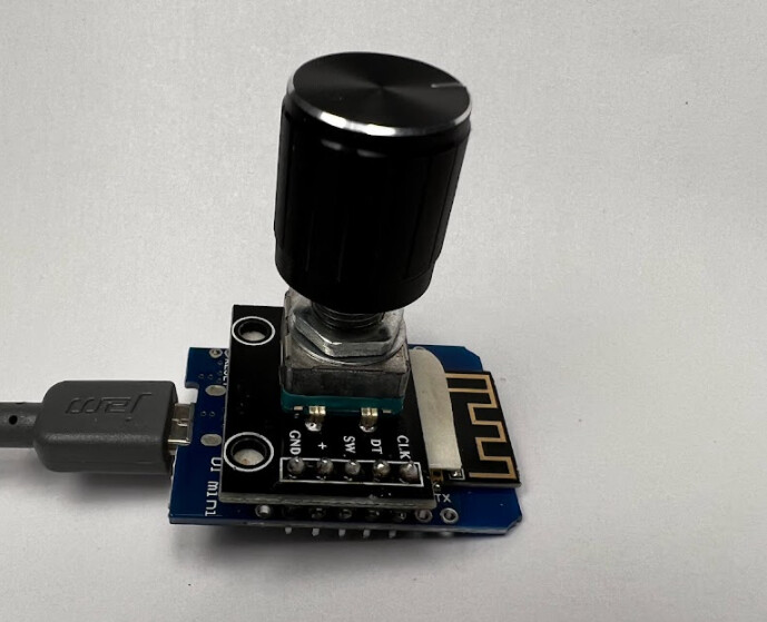
I’ve gotten a rotary encoder to work see this thread. It’s just like a potentiometer but works off pulses instead of resistance.
I have it controlling a google home volume (I use the google home max as a sound bar) currently and have dimmed lights with it. Goal being to have it there to adjust any device requiring variable input, lights, volumes, blinds, thermostats, etc. I would like to use it for multiple devices, it has a button push on the knob that would be good to iterate through a group of devices. Working at the moment but needs more time. I also need to come up with an enclosure for it and maybe small rechargeable battery.
That is not going to work for what @tmoehlman wants. Yours is a cool project though!!
Sort of similar to this I think GitHub - mikosoft83/pithy_screen_menu_system
After many false starts, I finally figured it out.
First, you’ll need to setup a custom float component and override the write_state method. I also added a separate method named digitalPotWrite, but you could put it all in the write_state method.
This file needs to be put in “/config/esphome/”.
Here’s what I did (I named it “CustomDigipotOutput.h”).
#include "esphome.h"
using namespace esphome;
#include <SPI.h>

byte address = 0x00;
int CS= 5;

class CustomDigipotOutput : public Component, public FloatOutput {
 public:
    void setup() override {
    // This will be called by App.setup()
    pinMode(CS, OUTPUT);
    }

    //write to Pot
    void digitalPotWrite(int value)
    {
      SPI.begin();
      delay(50);
      digitalWrite(CS, LOW);
      delay(50);
      SPI.transfer(address);
      SPI.transfer(value);
      digitalWrite(CS, HIGH);
    }

    void write_state(float state) override {
    // state is the amount this output should be on, from 0.0 to 1.0

    // we need to convert it to an integer first
    int value = state * 128;
    digitalPotWrite(value);
    }
};
Next you need to add the spi definition, output component and a service API to your Device configuration in ESPHome and install it.
# SPI pins definition
spi:
  clk_pin: GPIO18
  mosi_pin: GPIO23
  miso_pin: GPIO19
output:
- platform: custom
  type: float
  lambda: |-
    auto custom_digipot_output = new CustomDigipotOutput();
    App.register_component(custom_digipot_output);
    return {custom_digipot_output};

  outputs:
    id: thermostat_digipot
api:
  services:
    - service: control_pot
      variables:
        level: float
      then:
        - output.set_level:
            id: thermostat_digipot
            level: !lambda 'return level / 100.0;'
Assuming everything installs successfully to your device, you should be able to test it out using Developer Tools Services.
I used that to set the output on digipot for all values from 0 to 100 and measured the resistance with a multimeter.
Next step is to build an automation that will set the resistance based on a temperature per the 10K thermistor chart.
I hope this is helpful for someone.
11 Likes
Great! With some modifications, I managed to create an external temperature sensor emulator for an electric boiler. Emulated temperature sensor = Sonoff Basic R2 + MCP41100. I had to abandon the hardware SPI and use the software SPI, since the standard SPI pins are not available on this device.
Now I want to make it work together with the PID controlled thermostat.
Is anyone interested?
Hi @alexeivbaranov !
I’m doing something simular with MCP4151. I already have a solution for the PID controlled thermostat but Im really interested to learn how you used software SPI. I use this for PID HASmartThermostat and a teplate sensor where I take the outdoor temperature and modifies it with the pwm signal from the PID thermostat.
Im having a lot of trouble with my code and cant get my D1 mini to control the digipot. What microcontroller did you use? Could you post your code?
I’m also using this PID thermostat with PWM regulation. Now I want to emulate outdoor sensor temperature according value of control_output of PID thermostat. Boiler uses outdoor temperature to regulate its heaters - the lower temperature outside, the higher power it will consume.
I’m using Sonoff Basic R2: Using With Sonoff Basic — ESPHome
Nice device - cheap, has power supply on board, but requires little upgrade. Out of the box, it has two pins ready for soldering - GPIO01 and GPIO03 (TX and RX). GPIO02 is on the board (bottom side), but it’s a bit harder to get to than GPIO01 and GPIO02. So we have three pins, GND and 3.3v, should be enough to SPI. ESPHome recommends to use esp8285 board for this device.
Wiring (sonoff <> MCP41100):
3,3v to Vdd
TX (GPIO01) to CS
IO2 (GPIO02) to SCK
RX (GPIO03) to SI
GND to Vss
pins 5,6,7 - PA0, PW0, PB0 of digital pot
My boiler_digipot.yaml:
esphome:
  name: boiler_digipot
  platform: ESP8266
  board: esp8285

  includes:
    - CustomDigipotOutput.h

#
# ......
#

button:

  - platform: template
    name: Digipot PLUS
    id: digipot_plus
    on_press:
      - logger.log: Button PLUS Pressed
      - number.set:
          id: digipot_level
          value: !lambda "return id(digipot_level).state+1;"

  - platform: template
    name: Digipot MINUS
    id: digipot_minus
    on_press:
      - logger.log: Button MINUS Pressed
      - number.set:
          id: digipot_level
          value: !lambda "return id(digipot_level).state-1;"

  - platform: template
    name: Digipot SETLOW
    id: digipot_setlow
    on_press:
      - logger.log: Button LOW Pressed
      - number.set:
          id: digipot_level
          value: !lambda "return 0;"

  - platform: template
    name: Digipot SETHIGH
    id: digipot_sethigh
    on_press:
      - logger.log: Button HIGH Pressed
      - number.set:
          id: digipot_level
          value: !lambda "return 100;"

output:
- platform: custom
  type: float
  lambda: |-
    auto custom_digipot_output = new CustomDigipotOutput();
    App.register_component(custom_digipot_output);
    return {custom_digipot_output};
  outputs:
    id: boiler_digipot

api:
  services:
    - service: control_pot
      variables:
        level: float
      then:
        - number.set:
            id: digipot_level
            value: !lambda "return level * 100;"

number:
  - platform: template
    name: "Digipot level"
    id: digipot_level
    optimistic: true
    min_value: 0
    max_value: 100
    initial_value: 0
    step: 1
    mode: slider
    on_value:
      then:
         - output.set_level:
             id: boiler_digipot
             level: !lambda 'return x / 100.0;'
CustomDigipotOutput.h was created brutally. Looks ugly, but I was in hurry and decided to use simplest copy/paste:
#include "esphome.h"
using namespace esphome;
////////////////
Here I have copied the contents of the file SoftSPI.h from this link:
https://github.com/greiman/DigitalIO/blob/4e06d6c04f9007d81e1275522a84c37fbd458700/src/SoftSPI.h
SoftSPI.h requires DigitalPin.h, so it was copied/pasted from https://github.com/greiman/DigitalIO/blob/4e06d6c04f9007d81e1275522a84c37fbd458700/src/DigitalPin.h in place of #include "DigitalPin.h"
Please do not shame me but I did not want to figure out how to use external includes from custom ESPhome includes. Copied first, tried to compile - no luck, copied next etc :)
////////////////

////////
// And my code goes below, again copied/pasted from somewhere and updated with my requirements
///////
const uint8_t SOFT_SPI_MISO_PIN = 14;
const uint8_t SOFT_SPI_MOSI_PIN = 3; // GPIO03=RX
const uint8_t SOFT_SPI_SCK_PIN  = 2; // GPIO02
const uint8_t SPI_MODE = 0;
int __CS = 1; // GPIO01=TX

SoftSPI<SOFT_SPI_MISO_PIN, SOFT_SPI_MOSI_PIN, SOFT_SPI_SCK_PIN, SPI_MODE> soft_spi;

class CustomDigipotOutput : public Component, public FloatOutput {
 public:
    void setup() override {
       // This will be called by App.setup()
       pinMode(__CS, OUTPUT);
       digitalWrite(__CS, HIGH);
    }

    //write to Pot
    void digitalPotWrite(byte value) {

       int r;
       soft_spi.begin();
       delay(50);
       digitalWrite(__CS, LOW);
       delay(50);
       soft_spi.transfer(B00010001);
       soft_spi.transfer(value);
       delay(50);
       digitalWrite(__CS, HIGH);

    }

    void write_state(float state) override {
       // state is the amount this output should be on, from 0.0 to 1.0
       // we need to convert it to an integer first
       byte value = state * 255;
       ESP_LOGD("CustomDigipotOutput", "write_state %d", (int)value);
       digitalPotWrite(value);
    }
};
For now, I’m still have issues with wiring to boiler. Multimeter shows correct values on digipot outputs, but when connected to boiler, outdoor temperature values are unstable - flows around desired values. I’m not so experienced in circuit design, probably I have to use opto-isolator to isolate controller and boiler. Will try soon…
UPD. Added opto-isolator to digipot output. Got stable results, now I can change boiler performance according to control_output attribute of PID thermostat.
I’m using PC817B, I think it will work with PC817A also.
Wiring MCP41100<>PC817B according Voltage divider mode:
PA0 to 3.3v of controller
PW0 to PIN1 of PC817B (Anode)
PB0 and PIN2 of PC817B (Cathode) to GND of controller
PIN3, PIN4 of PC817B - to boiler TExt sensor. If the polarity is wrong, it will show the wrong temperature. Then just swap PIN3 and PIN4
1 Like
Great example code. How do I add mqtt support to this?
Yes, I have searched information on that page earlier but I think I need a working example with this FloatOutput component. I have found other examples with sensors but not with floatoutput.
Home Assistant is new to me with these yaml files.
Maybe my question is wrong.
What I need help with is to modify the yaml file to make it mqtt discovery.
By adding below code it will be using mqtt but I can’t see any config topic and no set value topic so I guess something is missing.
mqtt:
  broker: !secret mqtt_broker
  username: ${devicename}
  password: !secret mqtt_password
  discovery: true
This is what I had to add to get mqtt discovery woorking better.
number:
  - platform: template
    name: "Indoor set point"
    optimistic: true
    min_value: 0
    max_value: 1
    step: 0.1
    set_action:
      - output.set_level:
          id: thermostat_digipot
          level: !lambda "return x/100.0;"
  - platform: template
    name: "Indoor set point 2"
    optimistic: true
    min_value: 0
    max_value: 1
    step: 0.1
    set_action:
      - output.set_level:
          id: thermostat_digipot
          level: !lambda "return x/100.0;"
According to the esphome docs for mqtt (pointed to above)
All devices defined through ESPHome should show up automatically in the entities section of Home Assistant.
ESPHome still not supporting digipots, or even one common type? Thought this would be an obvious addition back in '19. It would be so easy to bring old stuff into the digital era with it, and million other applications.
Is it because digipots do not usually come in premade/breakout format or?
Please!
If this should be something like a feature request(?) you might wanna think to address it in the correct communication channel which should be the esphome githubs…
Yet you didn’t add it ![]()
Seriously this is an open source project. People scratch their own itches.
1 Like
Hello Tom,
I’m also trying to control an MCP41010 with your information. Unfortunately, I have no idea about C++ and can’t get any further. I connected the MCP41010 to a Wemos D1 mini and copied your code to the Wemos. Unfortunately, the resistance does not change. I have defined the following pins in the yaml file clk_pin:GPIO14
mosi_pin:GPIO13
miso_pin:GPIO12
What I’m still missing is the CS connector on the MCP41010. To which pin on the Wemos do I have to connect it and where do I define the CS_pin?
Unfortunately my English is not very good and I hope you understand me and can help me.
Thanks
greeting
Dieter
I did it  !
!
The archive contains everything you need to control the MCP410 ** via ESPHome.
Suitable for any ESP8266 with 4Mb ROM.

DigiPot.zip
5 Likes