Might be normal. Take your multimeter and measure the converter output voltage 40% and 100%. Is it 4V and 10V? Probably not. You can compare that to voltage of the “manual” dimming, what voltage levels you read when it turns off?
Also, while common Gnd works here, ideally you take benefit of optoisolator and have local gnd between Esp and converter.
From the 12V+ I get 12.03V, which is expected I think.
@Mikefila: I’ve implemented your recommendation as well and added frequency and gamma_correct. I’ve played around with it a little and found out, when I put the gamma_correct to “0.5”, I can go down to 1% and the light doesn’t turn off.
I’ll go on Vacation in a few days, so I can’t make anymore tests in the next month. But as soon as I’m back, I’ll test the initial setup with the buck converter. My goal is to not have an additional power supply to power the ESP. But if this doesn’t work out, I’ll have to power it with an additional power supply then.
So far I want to thank everyone in this thread . I’ve learned a lot on this little journey and I’m glad that we have this helpful community. My next project will be speed controlling a PWM Inline Duct Fan with ESP hehe.
I’ve set up my original plan with the buck converter, and it works! I’ve also changed the gamma correct in the ESP32 config to “0.6”. The output voltages of the PWM converter now are:
OFF or 0%: 0.59 V
1%: 0.87 V
25%: 4.51 V
50%: 6.68 V
75%: 8.38 V
100%: 9.88 V
I can still go down to 1% and the light doesn’t turn off. So, everything is working now as planned, without an extra power supply for the ESP32. The next step is to make a nice enclosure with a 3D printer because I can’t fit all the components in the old case anymore
Thanks for the tip. I’ve tested it but it doesn’t do anything. The output of the PWM converter stays at 0.59V at 0%. Also measured the PWM input, I’ve got 0 V at 0%, with and without the ZMZ-Parameter.
Can this be dangerous if the PWM conv. constantly outputs 0.59V at 0% or could it be normal? Just curious.
Alright I did some more research and tests. The 0.59V stays, no matter what I do. I figured out that the LED Driver has a threshold around 0.8-0.9V. Everything below is considered “off”. I also calibrated the PWM to Voltage converter with the potentiometer on the PCB to exact 5V with 50% PWM signal.
However, I must use the gamma_correct parameter in order to go down to 1% without the light turning off.
The 0.59V on VOUT can be caused by several reasons, but it’s harmless.
Possible reasons are:
Op-Amp Offset Voltage
Residual Charge or Leakage Currents
No Pull-Down Resistor on VOUT
LED Driver Interaction
Nonlinear Circuit Design
Internal Calibration or Design Limitations
I also found in the docs of the PWM to Voltage converter that it has an allowable error of 5%, which could be these 0.59V.
So far I think I’ll draw the line here, since these 0.59V aren’t causing any unintended behavior on the light.
Quick Update to my fellow Home Automation friends!
I started in a new position at the beginning of this year and luckily, I had the opportunity to chat with someone from the electronics department. I showed him my scheme, and he said that’s way too complicated.
Long story short:
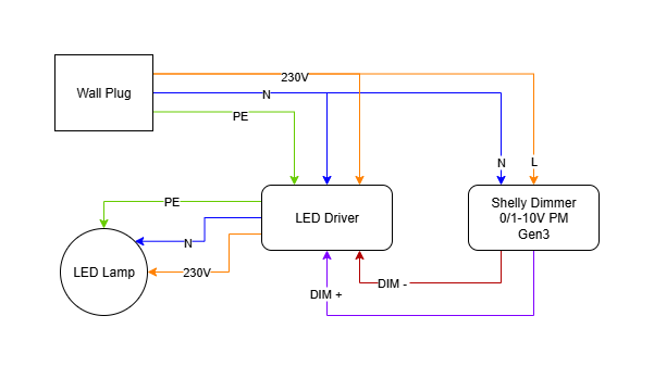
he gave me really helpful tips on how I could optimize this whole setup and make it a lot simpler. He recommended me to buy a Shelly Dimmer, and I couldn’t be happier! That’s literally all I needed haha.
I’ve posted my final scheme with the new dimmer setup below. Hope it helps someone if anybody reads this.