Their store is closed. But that project has come a long way since I last looked at it!
I’ve got one of these connected to a Wemos D1 mini to monitor my geyser. Here’s the code:
sensor:
  - platform: ct_clamp
    sensor: adc_sensor
    name: "Geyser Power"
    update_interval: 60s
    filters:
      - calibrate_linear:
          - 0 -> 0
          - 0.12 -> 17.4
      - lambda: return x * 230.0 / 1000;
    unit_of_measurement: "kw"

  - platform: adc
    pin: A0
    id: adc_sensor
3 Likes
Oh my god, someone followed the documentation. Good work buddy!
1 Like
It seems to be a rather unused resource!
Yeah, knew that, but I saw you were rolling your own so thought the actual software might help. I stumbled on IoTaWatt while looking at TED, Sense, Emporia, GEM, etc. Glad I did, I think it’s a great solution, and has been rock solid since install.
There’s also these:
Will interface to any SPI compatible microcontroller (including of course ESP8266) and is supported via ESPHome. Or use the MQTT software on their Github page.
Really nice because it provides multiple current clamps, voltage detection, phase, frequency, etc. etc.
1 Like
The ESPHome documentation (https://esphome.io/components/sensor/ct_clamp.html) uses the adc sensor platform to read the current/voltage value.
If I understand correctly:
- It updates the value outward (to HA) every update_interval.
- It has an additional parameter sample_duration to indicate how often the sensor entity is sampled for averaging the outward value.
If the adc sensor only updates every 60s (default) then the sample_duration actually reads the same value over and over for the whole 60s.
How does the update_interval of the adc sensor itself play into this?
1 Like
Thanks for the mention @AaronCake!
I just wanted to point out that the ESPHome sensor data for the energy meters is located here: https://next.esphome.io/components/sensor/atm90e32.html
Which model from the link did you use?
100A 50ma or 100A 1v?
50ma, I think.
Hi
I have bought the 100A 50mA CT Clamp from YHDC (SCT-013-000).
I’m using the EPS32S
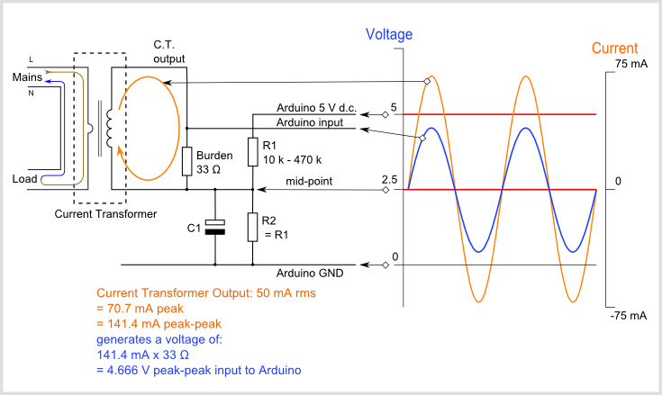
I would recommend this site which explains the electrical circuit.
https://learn.openenergymonitor.org/electricity-monitoring/ct-sensors/interface-with-arduino
if you use the 100A 50mA CT Clamp, don’t forget to get the 18 Ω for the burden resistor.
Additionally, I had to set the attenuation to 11dB for the ADC. else it was always in saturation.
  - platform: adc
    pin: A0
    id: adc_sensor
    attenuation: 11db
1 Like
Hi
I have done some further investigation.
as mentioned above, I’m using the 100A 50mA CT Clamp from YHDC (SCT-013-000) and the ESP32S
I have followed the implementation of the defined here
https://openenergymonitor.org/forum-archive/node/156.html
I have used a burden resistor of 18ohms as I’m expecting input voltage <3.3V
however, when I use the burden resistor, I cannot see anything
below graph is showing on the upper one, the Voltage from ADC (green) and Ampere (orange) from the CT clamp
the lower graph shows the power read from the CT clamp (green) and I read the power from a HLW8012 (orange)

I’m using a hair dryer to generate the load (with different speeds to make some variations)
the power read from the HLW8012 shows the power consumption variations as I change my air dryer modes.
however from the CTClamp, I can see that the power increase at first but I cannot see the variation. From the intensity, also no variations seen.
When I remove the burden resistor, I can see the variations on the intensity and the variations of the power calculated from the CT clamp.
however the ratio between the CT clamp power and the HLW8012 power is not constant.

I have tried many time but I couldn’t make the intensity go above the 2A.
I feel I’m reaching a saturation level where the ESP32 is not able to convert value.
to solve saturation, I understand we should use a resitance, but when I use the burden resistor, things are looking worse.
here is my code
sensor:
  - platform: ct_clamp
    sensor: adc_sensor
    name: "housepower"
    update_interval: 10s
    filters:
#      - calibrate_linear:
#          - 0 -> 0
#          - 1.810 -> 4
      - lambda: return x * 230;
    unit_of_measurement: "W"

  - platform: adc
    pin: 34
    id: adc_sensor
    name: "adc_sensor"
    update_interval: 1s
    accuracy_decimals: 5
    attenuation: 11db

  - platform: ct_clamp
    sensor: adc_sensor
    name: "intensity"
    update_interval: 1s
    unit_of_measurement: A
    accuracy_decimals: 5
any idea ?
Luj
Thank you thatguy_za. To get the current data in HA, anyone knows if the CT clamp output wires (red and white), can be conected directly to a NodeMCU 8266 pins? (I only need output values 0-3V)
Hello CT Guru’s… looking for some advice on CT clamps to buy.
I purchased a SCT013-020 but unfortunately it is too big to fit inside the junction box that contains the AC wiring. So I’ve looked at one of these YHDC clamps.
Could one of you fine people give me the thinking on using one of the above CT clamps connected to an ESP8266 NodeMCU.
Thanks, Mark
I would just go with a pzem004t v3 and save all the hassle for another project. Not only faster to setup (no calibration etc.) but also literally the same price as a coil (and it comes with a coil!). It also measures voltage, frequency beside current and all of that with a quite good accuracy (surely much better you can achieve with any coil because of the lack of RMS)
1 Like
Unfortunately disconnection of the wiring to install the CT is not an option, which is why I am looking at clip on CT units. Also, having a bare core isn’t allowed inside a mains junction box. Thanks anyway.
I use this one, it has clip on clamp and I have the unit outside of the FCU:
1 Like
Hi there… looks interesting. How did you connect it to HA?
Used an ESP32, but you can use a D1 mini or NodeMCU
You can use this using esphome:
Thanks again, I’ve ordered one of the units with the clip on CT.