I’m very curious about the new I2C bus that you discovered, mmakaay! It’s easy to think that this has to be used for the LED driver somehow, isn’t it?
Is the esp fw ready to upload to the light?
@airlychee Not yet. I nailed the white light settings and and now looking once more at the RGB light settings, because I saw some differences in color and measurements between my naive RGB implementation and the original lamp.
Also, I figured out how the front panel works, but I will have to write the code for that. When you don’t need the front panel, you might be able to use an intermediate setup, which only supports the lights. I will post it here when I got the RGB nailed too, which would bring the firmware to that stage.
I’m very curious about the new I2C bus that you discovered, mmakaay! It’s easy to think that this has to be used for the LED driver somehow, isn’t it?
@Smurf Nope, the LED driver is fully controlled by 2 GPIOs that act as a master switch for the LED circuitry (used in a simple digital mode: HIGH or LOW) and 4 GPIOs that control RGB versus white temperature mode and the color + brightness of the LEDs (all PWM-driven, so basically outputting different voltages to the LED circuitry).
One of the two I2C busses is for the front panel interaction (GPIO19/GPIO21).
The other bus (GPIO17/GPIO18) is connected to a small 8 pin IC that screems “EEPROM!”, but I haven’t been able to verify if it indeed is an EEPROM. The markings are really hard to read, but I managed to take a picture of them on my two devices. I found that the markings were different on the two devices, so I’m not sure what I am looking at here.
Here’s a picture I cooked up with this info and the location of the IC:

One working theory that I have going, is that this is a read only EEPROM, providing a unique device ID. The device boot messages have this line of output:
[20:27:01]08:00:00.200 [I] did=332985470 hostname=MiBedsideLamp2-7651
and such device ID must come from somewhere I’d say. It might be this IC that provides it.
4 in 4 out looks like an isolator, and 0x10 is typical for an ambient light sensor, is there something else on the touch panel area?
The 8 pin IC is on the main board inside the lamp.It is not on the touch panel. The touch panel is 100% clear by now, that is the other I2C bus.
For getting the lamp functional, this 8 pin IC is not that important BTW. An operational front panel and LEDs are already in reach. Still, would be fun to understand as much of the circuitry as possible.
I’ve created a drawing to document the progress on the ESP32 pinout mapping:

Update:
I soldered two leads to GPIO17 + GPIO18 and hooked those up to my logic analyzer. I was hoping to see some I2 signalling, but nothing came up. I fiddled with the front panel and changed settings and configuration options through the accompanying app. All of that did not trigger signals.
I did some tracing on the 8 pin IC and the layout seems compatible with the regular EEPROM pinout. This is what the pinout looks like, as far as I could trace it:

I can’t find a connection to the bottom two pins. They might be left floating, and are possibly pulled down by the IC. With the lamp powered on, I measure 0.0V on all the pins at the bottom.
I’ll leave this puzzle for now, going back to working on the RGB part.
floating those pins is normal if the intention is to activate a specific i2c slave address
I can’t really see the purpose of this I2C bus, then. Maybe an unused feature if this board is used for different models. Ambient light sensor as suggested, temperature sensor or microphone for “music flow”(or listening in on your bedroom activities…)
If it were something like an ambient light sensor, the component would have a totally different look. A little black box, buried deep inside the enclosing device is not really feasible for light sensing.
Very true. It could be a I2C bus repeater/buffer, but it doesn’t explain the floating output.
i2c eeprom chips use those pins to set their device address, so you can address 8 different chips on the same bus
Once I got my new firmware running, I will simply check if this indeed is an EEPROM by talking to it like it were one. That might be the quickest route to find out if it’s an EEPROM or not.
What I find curious is that A0 would be connected directly to ground, while A1 and A2 seemingly are floating. That’s a bit of a strange mix. All grounded or all floating would make more sense to me.
Made some progress on the RGB + brightness to GPIO output voltages functionality.
I did a load of measurements and wrote some python code with tests to see if I can come up with a good function that drives the LEDs in a backward compatible manner.
For those interested, the work so far can no longer be found on github, code has been superceded.
The RGB voltage measurements can be found in my spreadsheet.
Next steps: do some more measurements and fit these into the RGB script, then try to simplify the functions before implementing it in C++ in the ESPHome code.
One thing I noticed with my current naive first implementation (steering the GPIOs using values that one would normally use for RGBW(W) LED strips), is that the lamp circuit sometimes seems to reset.
In that implementation, I do set GPIO output to values that are close to zero, but the original circuit dips down to about 1.77V at most. The lower the GPIO voltage, the brighter the LEDs. My guess is that setting voltages below 1.77V might simply overdrive the circuit and cause brownouts.
Update:
Oh bugger, TIL. I just noticed that I have been measuring using the Brightness value in Home Assistant, while feeding it Brightness values. So what’s the different? well, Brightness value is 0 - 255, while Brightness is 0 -100. So the fact that I saw voltages that did not go below 1.77, was caused by setting the brightness to 100/255 instead of 100/100 

Tomorrow I’ll redo my measurements using the correct input.
Update:
I did a load of new measurements and here’s a set of measurements that shows that driving RGB will not be straight forward clean functions. Just like with the white light modes, there are some zones that can be recognized when graphing the values:

These are all at brightness 1 of 255, with R=255, G=variable, B=0.
Hey Maurice,
Great work on all of this. I’m currently trying to build a custom component to interact with the front panel.
On the voltages, wouldn’t it be more meaningful to measure the duty cycle of the GPIO pin over the voltage to the LED? I think just measuring voltage you could run into a few different issues.
Just 2c.
1 Like
Cool that you’re working on the front panel!
Since I’m mainly trying to come up with code to make the LED driving backward compatible, measuring voltages in the old and new situation to see if I do the correct things seemed good enough to me.
For the white temperature light, this worked very well, so I stuck to that method.
I must say, that because of the results that I get for the RGB LEDs (weird graphs requiring more and more measurements to reverse engineer), I am starting to lean towards hooking up another MCU to the LED GPIOs, to do some automatic measurements on duty cycles based on various color inputs. The whole “change light in HA and measure pins by hand”-thing is getting old quickly 
1 Like
I’m away from home this week but when I was poking around the device it seemed like the while LED’s are driven differently to the RGB LED’s. My probing around suggested that the RGB channels are driven using PWM vs the voltage based driver chips for the white channels.
1 Like
Yes, those are two different beasts alltogether, RGB and white.
It makes for a nice reverse engineering puzzle :-p
Once in a while, my lamp reboots spontaneously. I hooked up the serial console and waited for one of these crashes, and I saw the following on my console output:
[15:02:43]Guru Meditation Error: Core  0 panic'ed (LoadProhibited). Exception was unhandled.
[15:02:43]Core 0 register dump:
[15:02:43]PC      : 0x400d6cff  PS      : 0x00060130  A0      : 0x80163618  A1      : 0x3ffb1f00
[15:02:43]A2      : 0x3ffb8b90  A3      : 0x3ffd3658  A4      : 0x3ffd365c  A5      : 0x00008cc0
[15:02:43]A6      : 0x00050b23  A7      : 0x3ffb8058  A8      : 0xbaad5678  A9      : 0x3ffb1ea0
[15:02:43]A10     : 0x00000005  A11     : 0x3f40305c  A12     : 0x00000043  A13     : 0x3f4013a5
[15:02:43]A14     : 0x3ffd3364  A15     : 0x00060b23  SAR     : 0x0000000a  EXCCAUSE: 0x0000001c
[15:02:43]EXCVADDR: 0xbaad569c  LBEG    : 0x4000c2e0  LEND    : 0x4000c2f6  LCOUNT  : 0xffffffff
[15:02:43]
[15:02:43]Backtrace: 0x400d6cff:0x3ffb1f00 0x40163615:0x3ffb1f20 0x401636a9:0x3ffb1f40 0x400de3a5:0x3ffb1f60 0x400e0eb2:0x3ffb1f90 0x400eda41:0x3ffb1fb0 0x4008926d:0x3ffb1fd0
[15:02:44]
[15:02:44]Rebooting...
So a LoadProhibited exception while reading from memory location 0x3ffd3364.
A new puzzle to chew on. I will check my code to see if I might be doing bad memory stuff. I surely hope so, otherwise we might be looking at a bug in the underlying platform code.
Update:
Hrm, not my code:
0x400d6cff: esphome::api::APIServer::loop() at src/esphome/components/api/api_server.cpp line 67
0x40163615: esphome::Component::call_loop() at src/esphome/core/component.cpp line 61
0x401636a9: esphome::Component::call() at src/esphome/core/component.cpp line 82
0x400de3a5: esphome::Application::loop() at src/esphome/core/application.cpp line 72
0x400e0eb2: loop() at src/main.cpp line 265
0x400eda41: loopTask(void*) at /root/.platformio/packages/framework-arduinoespressif32/cores/esp32/main.cpp line 19
0x4008926d: vPortTaskWrapper at /home/paul/src/esp32-arduino-lib-builder/esp-idf/components/freertos/port.c line 143
Update:
I see various reboots here, quite annoying. It’s not directly clear where the issues are triggered, so I took back a step and now will run my lamp with a mostly empty esphome configuration. If that doesn’t show the crashes, I will add stuff one step at a time to see where things go haywire.
3 Likes
I have some hopes on new framework releases to get rid of some memory management issues. The crashes that I see all seem related to invalid memory access. I’m currently working on getting everything compiled, because the single core processor is a bit of a challenge.
One thing that I noticed is that there seem to be two different issues:
-
The connection of Home Assistant to the ESP32 is dropped quite often, because the ESP32 reports that the final TCP ACK for an ESPHome ping sequence is not received by the ESP32 (and kills the connection). In tcpdump I do see an ack though, so it;'s either not transported to the ESP32, or it misses out on the packet. Right after the ESP32 sends the TCP FIN sequence, Home Assistant will always successfully reconnect.
-
When I have the logging screen open from the ESPHome web terminal, then I do see ugly reboots of the device. When I don’t have any logging channel attached, the device seems stable. To test for reboots while not logging, I added the uptime sensor platform to the config. The below graph shows the uptime. Twice I had the logging console open, and those two times show up clearly in the uptime.

So still working on drilling this down. If I can get to the point where the device does not reboot, but loses its connection with Home Assistant once in a while, I am willing to accept that as a feasible setup. The connection loss in Home Assistant is irritating from a development standpoint, but it is not hugely disturbing for daily use.
Update:
I managed to hack and compile the firmware using [email protected] and [email protected], but unfortunately that did not change the disconnect and reboot behavior of the device  I just saw a few disconnects followed by a reboot. The reboot was still happening at
 src/esphome/components/api/api_server.cpp line 67 (which isn’t a surprise, since the esphome api code was not changed in the process, I mainly hoped for less disconnects triggering less reboots as a result).
Update:
Hello from deep down in the firmware code. I am in the process of debugging the recurring disconnects and I might have found something interesting. With extra debugging added, I see the following pattern:
SENSOR STATE IS PUBLISHED
[00:56:17][D][sensor:099]: 'Bedside Lamp Office Uptime': Sending state 462.02200 s with 0 decimals of accuracy
[00:56:17][VV][api.service:105]: send_sensor_state_response: SensorStateResponse {
[00:56:17]  key: 1910806034
[00:56:17]  state: 462.022
[00:56:17]  missing_state: NO
[00:56:17]}

A TCP ACK IS REGISTERED, SETTING BUSY TO FALSE
[00:56:17]-S: 0x3ffd35c8
[00:56:17]_sent() sets busy = false: 0x3ffd35c8
[00:56:17]_sent() end of function, busy = 0: 0x3ffd35c8

A TCP SEND IS REGISTERED SETTING BUSY TO TRUE (which  means: waiting for a TCP ACK)
[00:56:17]send() sets busy = 1, _pcb_sent_at=462060: 0x3ffd35c8

POLLING NOW CONTINUOUSLY SEES BUSY = TRUE
[00:56:17]-P: 0x3ffd35c8
[00:56:17][W][AsyncTCP.cpp:963] _poll(): _pcb_busy=1, now=462223, _pcb_sent_at=462060, _rx_last_packet=462056
[00:56:17]-P: 0x3ffd35c8
[00:56:17][W][AsyncTCP.cpp:963] _poll(): _pcb_busy=1, now=462723, _pcb_sent_at=462060, _rx_last_packet=462056
[00:56:18]-P: 0x3ffd35c8
[00:56:18][W][AsyncTCP.cpp:963] _poll(): _pcb_busy=1, now=463223, _pcb_sent_at=462060, _rx_last_packet=462056
[00:56:18]-P: 0x3ffd35c8
[00:56:18][W][AsyncTCP.cpp:963] _poll(): _pcb_busy=1, now=463723, _pcb_sent_at=462060, _rx_last_packet=462056
[00:56:19]-P: 0x3ffd35c8
[00:56:19][W][AsyncTCP.cpp:963] _poll(): _pcb_busy=1, now=464223, _pcb_sent_at=462060, _rx_last_packet=462056
[00:56:19]-P: 0x3ffd35c8
[00:56:19][W][AsyncTCP.cpp:963] _poll(): _pcb_busy=1, now=464723, _pcb_sent_at=462060, _rx_last_packet=462056
[00:56:20]-P: 0x3ffd35c8
[00:56:20][W][AsyncTCP.cpp:963] _poll(): _pcb_busy=1, now=465223, _pcb_sent_at=462060, _rx_last_packet=462056
[00:56:20]-P: 0x3ffd35c8
[00:56:20][W][AsyncTCP.cpp:963] _poll(): _pcb_busy=1, now=465723, _pcb_sent_at=462060, _rx_last_packet=462056
[00:56:21]-P: 0x3ffd35c8
[00:56:21][W][AsyncTCP.cpp:963] _poll(): _pcb_busy=1, now=466223, _pcb_sent_at=462060, _rx_last_packet=462056
[00:56:21]-P: 0x3ffd35c8
[00:56:21][W][AsyncTCP.cpp:963] _poll(): _pcb_busy=1, now=466723, _pcb_sent_at=462060, _rx_last_packet=462056
[00:56:22]-P: 0x3ffd35c8
[00:56:22][W][AsyncTCP.cpp:963] _poll(): _pcb_busy=1, now=467223, _pcb_sent_at=462060, _rx_last_packet=462056

UNTIL IT DECIDES IT IS A TIMEOUT
[00:56:22]_poll() sets busy = false after ack timeout: 0x3ffd35c8
[00:56:22][W][AsyncTCP.cpp:969] _poll(): Houston, we have an ack timeout 4
[00:56:22][V][api.connection:696]: Error: Disconnecting Home Assistant 2021.3.2 (192.168.100.135)
The weird thing in the pattern here, is that there is a send in the log that is coming AFTER the ACK that to me looks like the ACK for the send call. If the code handles these two events in the wrong order here (sometimes), then the timeout can be explained very easily.
Some signs that this might indeed be a code issue:
- The timeout is always on this step of the data exchange.
- The connection seems to work just fine. I do see the correct TCP flows when scanning the network at the Home Assistant side.
- When I hack the code to simply ignore the ACK timeouts, then the socket connection with Home Assistant is kept as-is and it is still very much functional. I get update and can change light settings, without running into issues. So disabling the timeout check, actually makes my device more stable

- It is also likely not Home Assistant that is breaking the network connection here, because the same kind of connection drops can be observed when viewing logging from the ESPHome web console. This means I have two endpoints that show the same behavior, making the network stack in the ESP32 more likely the culprit.
Unfortunately, one needs to sleep at some point, so I’ll continue this bug hunt tomorrow.
Update:
With some more debugging I am now 100% sure that there is a race condition going on, and that the ACK is processed before the AsyncTCP code has decided that it wants to process an ACK.

I color coded the console output and what you see is the red text, which is interrupted mid sentence by the green text. I also added timestamps (now = …) and those proof 100% that this is a race condition. The earlier logline in green has a later timestamp than the last bit of the interrupted red log line.
Going to cook up a fix and see if the upstream project can incorporate it!
Update: Issue created with AsyncTCP upstream
I created an issue ticket for AsyncTCP.
And I creaed a fix in a forked repo, which I described in another thread.
3 Likes
Only work and no joy for me nowadays. Illness in the family doesn’t really contribute on the positive side either, but I do follow your work with interest whenever time allows it, mmakaay. Could your latest finding possibly explain the erratic disconnection errors that Yeelight is famous for?
Sorry to hear that, all the best for you and your family.
The disconnect issue that I found could be the issue, but only if the standard firmware makes use of the same AsyncTCP library code. Maybe you could check your copy of the firmware, to see if your can find the AsyncTCP string in there (it’s a long shot, but if it is visible as a string, chances are high that they are using it).
My modified version of the library is performing great. Here’s the graph of my lamp uptime and connection for the last 8 hours:
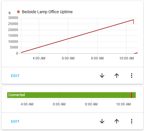
Only one recent disconnect, but that one might slightly have to do with me unplugging the device and moving it upstairs to my work desk there.
Having tackled this issue also gets rid of the spontaneous reboot issue. Not because the underlying issue is fixed, but because it is not triggered anymore. I’ll still look at fixing that reboot issue, but right now getting on with the actual implementation for the lamp’s RGB channels is a lot more tempting.
Thanks, mmakaay. When life serves you lemons, try squeezing it in your eyes to get the full experience
Searching with ‘Strings’ gives nothing when using “AsyncTCP”.
I did however split the bin-file into partitions using ‘esp32_image_parser’ giving me nine entries; nvs, otadata, phy_init, miio_fw1, miio_fw2, test, mfi_p, factory_nvs, core dump and minvs.
My plan was to have a closer look at these using Ghidra that has an ESP32-extension that disassembles and decompiles the files, but I am at very best a novice when it comes to coding. It looks like this probably fits your skills a lot better than mine.