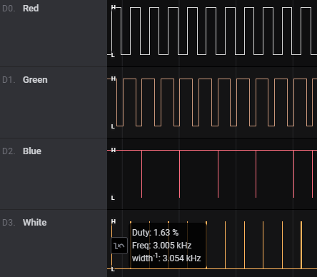
Started debugging the ledc frequency issues that I run into. I’ll document what I find in here.
First of all, I checked the console boot messages against the frequencies as used in my code. This shows:
[12:40:04][C][ledc.output:032]: LEDC Output:
[12:40:04][C][ledc.output:033]:   Pin GPIO13 (Mode: OUTPUT)
[12:40:04][C][ledc.output:034]:   LEDC Channel: 0
[12:40:04][C][ledc.output:035]:   Frequency: 3000.0 Hz
[12:40:04][C][ledc.output:032]: LEDC Output:
[12:40:04][C][ledc.output:033]:   Pin GPIO14 (Mode: OUTPUT)
[12:40:04][C][ledc.output:034]:   LEDC Channel: 1
[12:40:04][C][ledc.output:035]:   Frequency: 3000.0 Hz
[12:40:04][C][ledc.output:032]: LEDC Output:
[12:40:04][C][ledc.output:033]:   Pin GPIO5 (Mode: OUTPUT)
[12:40:04][C][ledc.output:034]:   LEDC Channel: 2
[12:40:04][C][ledc.output:035]:   Frequency: 3000.0 Hz
[12:40:04][C][ledc.output:032]: LEDC Output:
[12:40:04][C][ledc.output:033]:   Pin GPIO12 (Mode: OUTPUT)
[12:40:04][C][ledc.output:034]:   LEDC Channel: 3
[12:40:04][C][ledc.output:035]:   Frequency: 10000.0 Hz
These are the correct frequencies. This means that LEDCOutput::dump_config() is presenting the expected data here.
Also, each GPIO got its own unique PWM channel assigned, so the problem is not misassignment of those channels (as I expected, since I do measure distinct duty cycle levels on each output). So far so good.
I tried setting the frequency of the white light GPIO to 8888 Hz, to make sure that it’s this GPIO’s configuration that taints the blue output. This confirmed that it’s indeed the white light’s frequency that is used for blue. By turning on the white light mode, I could also confirm that the white light GPIO is also using that configured frequency.
I tried disabling the i2c components, just to be sure. As expected, this had no influence on the results.
Next stop was adding some extra debugging output to LEDCOutput::setup(), to check if the correct parameters were sent to the arduino-esp32 library. This looked good:
[13:03:36][W][ledc.output:029]: Attach channel 0 to pin 13 with frequency 3000.000000
[13:03:36][W][ledc.output:029]: Attach channel 1 to pin 14 with frequency 3000.000000
[13:03:36][W][ledc.output:029]: Attach channel 2 to pin 5 with frequency 3000.000000
[13:03:36][W][ledc.output:029]: Attach channel 3 to pin 12 with frequency 10000.000000
So, at this point, it looks like I have to drill deeper, down into the arduino-esp32 esp32-hal-ledc implementation. Unfortunately that is harder to debug, since I’m using pre-built library code here. Need coffee…
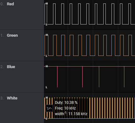
The coffee made me think: what if I define the white light frequency before the R, G, B frequencies? Well, that looked promising. The RGB GPIO’s used 3 kHz. However, this is what I saw when I turned on the white light:

Now an RGB channel clearly affected the frequency of the white light channel, which was now running at 3 kHz instead of the configured 10 kHz.
Curiously, I updated WRGB to respectively 10, 1, 2 and 3 kHz.
The result was a frequency of respectively 1, 1, 3 and 3, kHz.
So it looks like things go awry in pairs here. Let’s see when happens if I assign the pins in the order BGRW. This means the frequencies are respectively 3, 2, 1 and 10 kHz.
The result was a frequency of respectivley 2, 2, ? and 10 khz (the red channel couldn’t be read successfully and showed as constant HIGH, but I bet it was running at 10 kHz.
So based on this, it looks like every second ledc assignment sets the PWM frequency for both itself and its previous channel. This does shift attention to the PWM channel setup as described in the LEDC Chan to Group/Channel/Timer Mapping of the arduino-esp32 code. Looking at that, the four ledc PWM channels are mapped like this:
** ledc: 0  => Group: 0, Channel: 0, Timer: 0
** ledc: 1  => Group: 0, Channel: 1, Timer: 0
** ledc: 2  => Group: 0, Channel: 2, Timer: 1
** ledc: 3  => Group: 0, Channel: 3, Timer: 1
Interesting, right? Four channels, however the timers are overlapping. I find it very likely that it is simply a fact that the timers are shared for each pair of channels, and that you can therefore not set the frequencies independently. If this is the case, then the following configuration might be a working hack to get the outputs to behave:
  - platform: ledc
    id: led_ledc_timer_sharing_bugfix
    pin: GPIO12
  - platform: ledc
    id: led_white
    pin: GPIO12
  - platform: ledc
    id: led_red
    pin: GPIO13
  - platform: ledc
    id: led_green
    pin: GPIO14
  - platform: ledc
    id: led_blue
    pin: GPIO5
Well, look at that:

This fixes my issue, in quite a hacky way. The channels are now all running at their required frequencies. And of course, now I go back to the ledc component documentation, it clearly states:
channel ( Optional , int): Manually set the LEDC channel to use. Two adjacent channels share the same timer. Defaults to an automatic selection.
So after a bit of a round trip, I now understand the exact meaning of this snippet from the documentation and can therefore fix my setup by hard-coding some channels in the device yaml file. I went along and also moved the frequencies into this file. Check out the new example.yaml file for the updates that I did, and specifically the ledc output changes
(esp-ecially you @tabacha, since you were brave enough to flash your device already  update the code and the YAML, which now includes
 channel + frequency, for the new goodness.)


