Congratulations!
Re 3D printing, have a look at Reveni Labs - they’re using MJF printing to great effect at a reasonable scale.
Congratulations!
Re 3D printing, have a look at Reveni Labs - they’re using MJF printing to great effect at a reasonable scale.
Hi everyone!
We’re currently in the middle of designing the next hardware revision, and we’re at a point where we’d really value your input and feedback. As a starter, we’ve made the following high-level visualization.
A couple of points for context;
Despite being interested in what you all think of this approach we think is a major step in the right way of incorporating feedback and achieving the ‘ultimate’ multisensor, we also have one very distinct question;
do you think it would cause trouble that the ‘3.3V’ we providing to the board connector (for other boards such as sound monitoring, mmWave presence sensing, etc.) is actually somewhere between 1.8V-3.3V?
If you do, we would have to step-up the voltage of the CR123A. This comes at a large cost however; an efficiency of around 65% of most step-up converters (even the TPS6129 (datasheet)). I estimate that this roughly cuts battery-life in half. Does having a ‘real’ 3.3V weigh up to that?
Tough question. I think most of the circuits will hold a lower voltage, but as you are in a open-source project, the risk is that somebody will need more than 1.8V.
A former boss of mine has a said : “If there is a doubt, there is no doubt”
But in fact he was most a commercial than a electronic designer.
Finally you said “achieving the ‘ultimate’ multisensor”. So if in fact your product is highly and also easly configurable, you have to get a solid base.
As I understand you are opened to other power sources. So the drop of battery life, of CR123A, is it really a problem ? Also, think about if you want a :
-rechargeable battery powered device
or
-a wired device with battery backup
A few notes as a layman
removes the air-pressure sensor
I plan to use air pressure trend to make weather predictions, and trigger things.
I would use it outside for a house cyclones happen to trigger covers, and also inside labs were positive pressure should be maintained for cleanliness, trigger blowers.
power - depending on all the features, I would like to be able to disable LEDs, buzzers, and sensors not in use, thereby reducing power draw. Besides wired, I would like to use rechargeable battery with points exposed, so I can trickle charge them from a solar panel. I could see a dozen or so distributed across a property with solar panels would come handy.
price - it is always hard to set price. What would it cost me to get most of the features you provide in this device? I would say that is at least two or four devices. Could I get them for less than €60? I doubt it.
Hi @nathan.tarillon and @info4hx4,
Thanks for your viewpoints and input; greatly appreciated. It has been a busy week, but I’ll make sure to come back next week with a more concrete and slightly altered approach based on your replies.
Have a nice weekend!
Hello, I see a good point in choosing the E73-2G4M08S1C for v2, as, in top of zigbee, is also Thread capable. On my side, I’'ve been thinking for a while about something similar based on a close relative, the e72-2g4m20s1e, which would be one of the best in terms of range. Already bought some of them, looking now the software part, the ptvoinfo firmware looks interesting, but not open source, and relying on its creator for new capabilities. There’s also the zigbee stack from TI (as it’s in fact mainly a cc2652 inside)…
In terms of firmware, don’t forget the repeater (optional) ability for devices that would have an external power supply (solar, mains)
I would recommend to stay away from 1.8V domain. Even if it is one of the standards noadays most of hobbist sensors use 3.3V or even 5V
Just from my gut feeling I think you can use a 1S lipo battery with a very low dropout voltage regulator (you have a lot of around 50mV). This might allow you to use the battery down to 20% of the charge. I would also tie the buck converter of the radio (if it has) directly to the battery. Voltage drops during transmision should not be a problem as you are using a lipo which have a very high discharge rate.
I would stay away from swiched supplies appart from the one from the radio.
I would also guarantee a fixed voltage. I think it will be superfrustrating the feedback from people about sensors stopping working or behaving differently at different battery state of charge or voltage.
With a proper power path you do not need a power source selection and charge the battery at the same time as suppling the system from the USB. This is an example:
When the battery is not connected the charger will act as a regulator so it is optional.
If you want to add solar panel support just connect it in parallel to the USB connector with Schottky diodes in series in both. If it is oversized you don’t need mppt (as in the huge majority of these kind of devices)
I think it is a nice project. I see as the biggest challenge by far to create a SDK that allows people to interface their own sensors.
Hi @dim6003! Yes, there are lots of options. Without going in a lot of detail, today we at Homr made some very significant progress with our next hardware design; the component selection is done and the basic schematic is made.
We decided to still go with Minew’s MS88SF21. Just like the Ebyte, it contains an nRF52840, thus also supporting Thread, Bluetooth, Matter, etc. The Ebyte’s are all LGA (Land Grid Array) with pins not accesible. While this is not a problem with Pick-and-Place, it poses challenges during development. All pins available on the outside are Low-Frequency, Standard-Drive pins and thus not suitable for the use-case of I2C, SPI, PWM or other.
Regarding the repeater abilities; that’s certainly on our to-do list! Thanks for your input! Oh, by the way, you do know we open-sourced our software based on the nRF Connect SDK right? It shows a great example of using Nordic Semiconductor’s SDK with the ZBOSS stack.
Hi @Pidjey! This would be a great approach if there’s always a LiPo connected. But that being the case depends on the LiPo module being connected to the broken out pin header. As a result, we’re forced to be a little more explicit.

Please note that only one power-board can be connected at the same time; so it’s either the CR123 OR LiPo board that is connected.
Do you or anyone else, based on this new insight, have any other suggestions? Thanks for your feedback!
As i already said even if there is not a battery it works the same and it is optional. I didn’t invent anything, it is just a standard scheme and i would say the most common for portable devices.
Hi @JVKran - I’m the order you shipped off to the US the other week, I got the device and am very impressed, great job. looking forward to watching your project move forward.
Hi everyone!
We’re quite far with developing hardware version two, and we’re keen on hearing what you think about it. Below are some pictures attached.
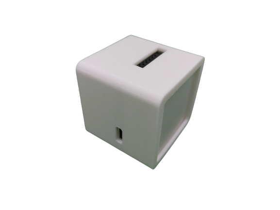


The main board, let’s call it the motherboard, contains only power-supply and multiplexing chips, as well as a button, USB-C connector, rgb-led and pin headers. Hidden behind the cover are two pin headers to which the illuminance sensor and PIR-sensor are connected.
One can have both a battery and USB-C cable connected; USB-C has priority over the battery. The battery-board is modulary connected to the motherboard through a pin-header, but we’re still tweaking this part. As a result, we need one more sub-iteration before being able to show off everything.
The hat pictured above, contains the temperature, humidity and air-pressure sensor.
We’re interested in your opinions!
Hi,
any date to get 5 of this boxes?
With best regards
Gerhard


