Epever RS485 + Elfin EW11 WiFi Modbus (or MQTT)

Solution updated below for Elfin EW11 and EPEver eBox-Wifi-01 in August 2021 for Modbus changes in core 7.1


How-to connect an Epever / Epsolar Tracer solar charge controller to Home Assistant. The output is RS485 via RJ45. The Epever eBox-WIFI-01 I tried first was bricked when attempting a by-the-book firmware update before I had a chance to test it with HA. Since I had a bad experience with that piece of hardware, I picked up an Elfin EW11, which also does wifi to RS485/Modbus.

Of note, the EW11 has the following protocols on the wifi side:

  • Tcp server
  • Tcp client
  • Udp server
  • Udp client
  • Mqtt
  • HTTP
  • Telnetd
  • WebSocket
  • Ali IoT

Other than avoiding Ali Iot, iā€™m not all that particular about which one works. However, the default Tcp server or MQTT seem like the best options. Unfortunately, I havenā€™t been able to get either working. I thought it would be simple, like in the thread belowā€¦

Continuing the discussion from Modbus TCP:

TCP Server / Modbus

Starting off, hereā€™s my modbus config in HA:

modbus:
  - type: tcp
    host: 192.168.1.232
    port: 8899
    name: hub1
  - type: rtuovertcp
    host: 192.168.1.232
    port: 8899
    name: hub2

I have 2 hubs set up for testing purposes. Iā€™m not sure which is correct for the Epever charge controller (CC).

Sensor section of configuration.yaml
  - platform: modbus
    registers:
      - name: Bank 1 Voltage
        hub: hub1
        unit_of_measurement: V
        slave: 1
        register: 0x3004
        register_type: input
      - name: Bank 1 Vx
        hub: hub2
        unit_of_measurement: V
        slave: 1
        register: 0x3004
        register_type: input

The CC modbus register manual [PDF] I found has the following statement:

Communication protocol is standard Modbus-RTU protocol.

This introduces a fork Iā€™m not sure how to traverse. I donā€™t know if HA should see TCP or RTU after being output from the EW11, so Iā€™ve tried both.

The EW11 manuals have a single mention of RTU in the UART section:

ā—† NONE: Default: None, transparent transmission, the received UART data will be directly sent to network.
ā—† Modbus: Modbus RTU to Modbus TCP.
ā—† Frame: Enable auto-frame function. Relevant parameters are set in Frame command.

Iā€™m not completely sure how to interpret that. If I set the Serial Port protocol in the EW11 to None, does that mean it passes raw RTU, in which case I would guess configuration.yaml should be set to rtuovertcp? If I set the Serial Port Protocol to Modbus, does HA want to see tcp in configuration.yaml? I donā€™t know, but Iā€™ve tried all 4 permutations with no success.

Configuration - Home Assistant

Hereā€™s the Serial Port Settings for the EW11:

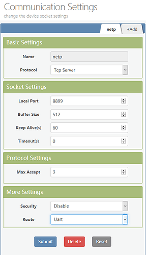
Hereā€™s the settings screen for the Tcp server:

MQTT

I can configure the MQTT settings in the EW11 for it to connect to the Mosquitto broker Add-on in HA. As well, the logs show that it connects successfully. However, nothing new shows up in MQTT (devices, entities, etc.).

EW11 MQTT settings:

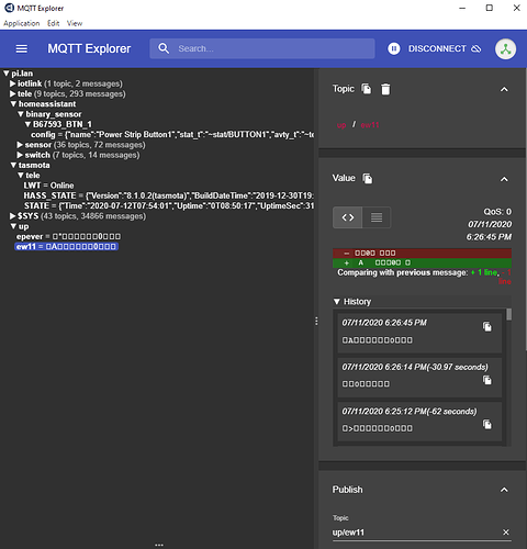
Since it was connecting, but not showing up, I pulled up MQTT Explorer, and connected to Mosquito broker. The topic shows up under ew11, but something is wrong (the epever topic is a remnant from other failed tests):

Inconclusion

Soā€¦ Iā€™ve been working on this for a lot of hours ā€“ juggling configurations as many different ways as I can think of, but Iā€™m stumped.

Any ideas for getting this going in TCP/modbus or MQTT (or anything, really)?

Oh, I did have to wire a custom connector for this. Iā€™ve gotten mixed information about the polarity of the A and B side of the RS485 connection. Iā€™ve tried it both ways, but have mostly been conducting tests wired according to the Epever manual (linked above).

Edit: Notes now that itā€™s working

  • Experienced multiple instances of settings not being applied after a save (ā€œSubmitā€), and not even being applied after a soft restart. The settings would appear correct in the UI, but not actually be applied. This sometimes appeared to be resolved by a power cycle, was sometimes resolved by uploading a known-good configuration file (Others ā†’ Backup ā†’ Restore), and perhaps even a factory reset (I believe pin 4 is the reset pin, and needs to be held down for something like 10 seconds while powered up).

  • The EW11 Manuals have a hard-coded link to an outdated file. It is to a .zip archive with a bunch of resources on modbus, and a few other things. This is the correct download page.

  • Modbus polling tool. The files in the link above also contain the most useful modbus app I found, as well as an activation that isnā€™t available if you download directly from the publisher. The UI isnā€™t necessarily intuitive, but it exposed data others didnā€™t. Hereā€™s the quickstart guide at the developerā€™s website.

I have the following in the Sensor section of configuration.yaml:

        slave: 1
        register: 0x3004

Iā€™m not sure how to tell whether these are correct. The Epever manual lists the register addresses in 4-digit format (e.g., 3004) in the PDF linked above. But it also mentions the 0x3004 format elsewhere. Iā€™ve tried it both ways. Since these donā€™t look like anyone elseā€™s values from other examples, Iā€™m wary that these are incorrect, but not sure what to change them to.

Edit: Pretty sure I have to figure out how to translate this CC infor into register values HA can handle:

  1. Register address uses hexadecimal format, the base address offset is 0x00.
  2. All 32-bit-length data uses two 16-bit registers to represent (L and H register,respectively), for example,the value of the array rated power is 3000, data multiple is100, the data of L register (address 0x3002)is 0x93E0 and the data of H register(address 0x3003) is 0x0004.

But I must confess that I havenā€™t yet wrapped my brain around all of it.

Looking at the Modbus sensor docs with a very confused facial expression:

scale
(float)(Optional)
Scale factor (output = scale * value + offset).
Default value:
1

offset
(float)(Optional)
Final offset (output = scale * value + offset).

Thanks for coming back with all the information you haveā€¦nicely documented!

I found this manual here

I canā€™t find any details in that document telling me what registers to read or write to?

Without that information I canā€™t really give too much to help you I feel? Where did you come up with your sensor register hexadecimal? In my use case the register is a decimal value so you can use a hexadecimal converter like this one which gives me a register value of 12292.

But first we need to get on the right page and find out what registers to read or write to for your device? By way of example, my PLCā€™s programming software allows me to read all the registerā€™s, coils, etc hexadecimal and decimal values from the program interface which is very convenient. Normally devices like yours will list the registers, coilsā€¦etc which you can safely interact with in the manual however not so in the manual I can find?

EDITā€¦bit more searching and found this which also has a link to the modbus documentation

I think this PDF is the one which answers those questions. The site has an expired SSL cert so it will probably throw a browser warning. Itā€™s listed as v2.5, whereas the link at the end of your post says v1.1. Iā€™ve seen that doc too, and I think itā€™s the one which has the A-B connections for modbus reversed.

Okay, I had the A-B lines reversed in the recent tests. After downloading a Modbus scanner (if anyone knows of a better one, please recommend), I was able to confirm the correct orientation. So now bytes are flowing, but Iā€™m still a bit hazy on how modbus works. Iā€™ll keep trying to chase down the magic words, but if someone with more modus experience can help me up the learning curve, that would be appreciated. Until then, hereā€™s the latest:


Error from modbus scan:

0x02 - ILLEGAL DATA ADDRESS

The data address sent in the query is not an allowable address for the server (or slave). More specifically, the combination of reference number and transfer length is invalid. For a controller with 100 registers, a request with offset 96 and length 4 would succeed, a request with offset 96 and length 5 will generate exception 02. A request for offset 200 will also produce this exception.

Edit: The 0x02 error is from having the Slave ID set to 1. If I set it to higher values, I consistently get a ā€œError, Timeout - No response to pollā€ error:

[14:17:12] Error, Timeout - No response to poll
[14:17:08] => Poll: C8 01 00 03 00 60
[14:17:05] Error, Timeout - No response to poll
[14:17:01] => Poll: C8 02 00 95 00 64
[14:16:58] Error, Timeout - No response to poll
[14:16:54] => Poll: C8 02 07 CF 00 64
[14:16:22] Error, Timeout - No response to poll

Still not able to get a successful poll.

In one of the Epever modbus register lists I should be able to get battery V on hex 3104 (dec 12548). On the other PDF, it should be at hex 331A (dec 13082). Whether I poll those registers, or a range including them, I get the timeout error from above.

Soā€¦ HA canā€™t be getting good modbus data, and itā€™s probably something in the EW11 config.

Since Iā€™m not able to get anything but timeouts when connecting via TCP through the EW11, it seems increasingly likely that something like this (default setting) Serial Port setting might need tweaking. But Iā€™m about out of ideas again.

comm-settings

I found an RS485 to TTL adapter at the bottom of a drawer. Taking the EW11 out of the loop, I learned some things, but havenā€™t solved anything.

The first thing I learned, via the Epever Windows app, is that the [serial test] connection is working. I get live data from the Solar Controller ā†’ RS485 to TTL ā†’ TTL to USB:

The next thing I learned is that none of the default polling on any of the 3 modbus polling apps get anything back. They all timeout. The one exception is if I send a command with the hex string:


That actually gets data back.

From the v2.5 PDF:

For example:

Read battery parameterļ¼ˆbattery type: user rated voltage level: 12V

Send commandļ¼š

01 03 90 00 00 0F 28 CE

Analysis ļ¼š
01 device ID
03 function code
90 00 the start bit of the address
00 0F the number of the address
28 CE CRC

Unfortunately, this is a kludgy test setup, and I canā€™t connect it to HA without running ethernet cable halfway across the planet.

Nice progressā€¦I will add that all my PLCā€™s are connected via ethernet cable so it is worth considering testing (temporary ethernet cable) to prove (or not) HA is working via that initiallyā€¦move on to your wifi adaptor after that?

I had the same thought, and got data to show up in HA (via eth to USB) about 10 minutes before your reply.

Overview - Home Assistant

Other than switching from the connection from TCP (over wifi) to my crazy chain of adapters, the only thing I remember changing was
From

        slave: 1

To

        slave: 01

That test will have to wait for another day!

1 Like

Awesomeā€¦very nice result for your efforts. If the wifi is problematic is it out of the question to wire this permanently or is wifi a must?

Iā€™d hate to say itā€™s 100% necessary until I have wifi working, but theyā€™re not normally in the same building, so wireless makes good sense. :sweat_smile:

If I canā€™t get wireless working, Iā€™d still have to replace this spaghetti mess of dev/test boards and exposed wires with a different wired option. So fingers crossed the wireless will get sorted.

1 Like

Hope so for you thenā€¦in any case you know it can be done to read your sensors in HA by all your hard work now. Fingers crossed the wifi adaptor works seemlessly.

1 Like

Not sure what actually fixed it, but itā€™s working now. I did a factory reset on the EW11 before the start of the day. It doesnā€™t seem like I did anything else that I didnā€™t try yesterday, but Iā€™ll take luck over understanding (for now)! The working settings ended up being very close to factory defaults. I think all I changed was Protocol from None to Modbus and Local Port from 8899 to the standard modbus port, 502.

My best guess is that there was a problem in the wiring in my initial attempts. It was common to see no data received when checking the EW11 status page. Iā€™m pretty sure I had all of the settings the way they ended up working multiple times before it actually worked. I basically stopped troubleshooting after I got it working, so Iā€™m not even sure what changes would break it (Local Port, etc.).

Working HA config

Configuration.yaml (modbus):

modbus:
  - type: tcp
    host: 192.168.1.232
    port: 502
    name: hub1
  - type: serial
    name: hub2
    method: rtu
    port: /dev/ttyUSB0
    baudrate: 115200
    stopbits: 1
    bytesize: 8
    parity: N

Note on above: I left the serial hub lines in there in case someone needs them, but theyā€™re not actually active in my system.

Configuration.yaml (sensors):

  - platform: modbus
    registers:
      - name: Battery
        hub: hub1
        unit_of_measurement: V
        slave: 01
        register: 13082
        register_type: input
        scale: 0.01
        precision: 2
      - name: Solar #3100
        hub: hub1
        unit_of_measurement: V
        slave: 1
        register: 12544
        register_type: input
        scale: 0.01
      - name: Solar Power L # 3102
        hub: hub1
        unit_of_measurement: W
        slave: 01
        register: 12546
        register_type: input
        scale: 0.01
      - name: Solar Current # 3101
        hub: hub1
        unit_of_measurement: A
        slave: 01
        register: 12545
        register_type: input
        scale: 0.01
        precision: 2
      - name: Load # 310E
        hub: hub1
        unit_of_measurement: W
        slave: 01
        register: 12558
        register_type: input
        scale: 0.01

Note on above: thereā€™s more data available, these are just the ones I was interested in. See the linked PDFs in the OP for more. Commented values are the hex values from the PDF, and the registers are the decimal equivalents.

Working EW11 Config

GitHub Gist Page | Direct download: ew11-config.xml (Probably want to change SSIDs and passwords)

I still want to get MQTT working, and also set up a couple switches through modbus or MQTT. Iā€™ll try to document further, but Iā€™m on to other projects first. One thing I definitely need to record is if the Blue (3 & 4) or Green (5 & 6) wires actually correspond to modbus A+. Epever lists them differently in different places, and I never found a definitive list which corresponds to the various model numbers.

2 Likes

Excellent! Maybe the factory reset after all your initial testing and reversed A-B lines was just what was required. I think anyone reading this will easily be able to use your process to help them get their project up and running.

I have reason to believe there is an EW11 firmware bug where the settings do not fully apply, even after a soft restart. Something with the memory perhaps. Will add a tip to hard restart in the case of problems to the notes in the OP.

1 Like

Iā€™m still not sure what fixed it, but the factory reset seems most likely. I had reversed the A-B lines dozens of times in testing. It eventually became clear that the settings were not actually taking hold, so I wasnā€™t observing the actual results of various settings/tests I thought Iā€™d done.

The EW11 can be found for about half the price of the Epever wifi box, and is a lot more flexible. They also seem to be actively releasing firmware updates, so maybe these glitches will be resolved. The Github Gist and HA config in the solution post should get folks going quick enough to not have to mess with a million saves and restarts. :laughing:

I still canā€™t get MQTT to receive any modbus data. Messing around with that again for an hour is partially what confirmed the settings-not-applying issue.

Now I just have to replicate the process for my Renogy inverter ā€“ which has RS485/modbus, but they wonā€™t share any of the information, and just want to sell their proprietary bluetooth dongle which only works with their proprietary phone app. :face_vomiting:

Oh well, I learned enough with this detour that I might actually be able to reverse-engineer the registers on that one. :crazy_face:

Hahaā€¦best of luckā€¦inverters are often very much locked down so do your research well on that project.

Thanks this helped me a out a lot. I wrote up most of the ICD into this post to help people

2 Likes