I would like to share how finally I was able to make it work with below project from : paveldn → GitHub - paveldn/haier-esphome: Haier ac integration for ESPHome
and Haier AC’s (2 different types).
Initially I was using cheap esp8266 board from aliexpress. I had some old board: WeMos D1 Mini Pro V3.0 NodeMcu 4MB
and I was trying to upload soft there.
For this board i used below yaml config:
esphome:
name: ac-sypialnia
name_add_mac_suffix: true # optional, adds MAC to device name
friendly_name: AC_SYPIALNIA
esp8266:
board: d1_mini
Wi-Fi with fallback AP
wifi:
ssid: !secret wifi_ssid
password: !secret wifi_password
ap:
ssid: “ESP8266_Fallback”
password: “fallbackpassword”
Enable UART logging for debug
logger:
baud_rate: 0
level: DEBUG
OTA for future updates
ota:
- platform: esphome
API for Home Assistant
api:
Web server for testing
web_server:
UART for Haier AC communication
uart:
- id: ac_port
tx_pin: 1 # GPIO1 (hardware TX)
rx_pin: 3 # GPIO3 (hardware RX)
baud_rate: 9600
climate:
- platform: haier
id: haier_ac
protocol: hOn
name: Haier AC
uart_id: ac_port
wifi_signal: true
display: true
visual:
min_temperature: 16 °C
max_temperature: 30 °C
temperature_step: 1 °C
supported_modes:- ‘OFF’
- HEAT_COOL
- COOL
- HEAT
- DRY
- FAN_ONLY
supported_swing_modes: - ‘OFF’
- VERTICAL
- HORIZONTAL
- BOTH
supported_presets: - AWAY
- BOOST
- SLEEP
on_alarm_start:
then:- logger.log:
level: WARN
format: “Alarm activated. Code: %d. Message: "%s"”
args: [ code, message ]
on_alarm_end:
then: - logger.log:
level: INFO
format: “Alarm deactivated. Code: %d. Message: "%s"”
args: [ code, message ]
on_status_message:
then: - logger.log:
level: INFO
format: “New status message received, size=%d, subcmd=%02X%02X”
args: [ ‘data_size’, ‘data[0]’, ‘data[1]’ ]
- logger.log:
Include local Haier component
packages:
local_haier: !include configs/external_components/local_haier.yaml
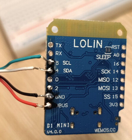
it worked like charm. When I was excited that it worked, I decided to equip the remaining air conditioning units with similar ESPs. However, for some reason, I bought slightly different ones this time — a newer model, version 4: WEMOS D1 Mini V4.0.0 TYPE-C.
…and that’s where the problems began. I couldn’t get any response from the AC at all.
[14:36:49.146][I][haier.climate:096]: Answer timeout for command 61, phase SENDING_INIT_1
[14:36:53.578][I][haier.climate:096]: Answer timeout for command 01, phase SENDING_FIRST_STATUS_REQUEST
It’s worth noting here that at that time, my pin configuration in the YAML file was identical to the previous board — I was trying to use RX/TX.
I spent a lot of time experimenting, trying different pins, e.g. tx_pin: 15 and rx_pin: 13.
Sometimes it would start working, but only in certain situations. I had to perform a kind of “startup procedure.”
When I connected only the ESP board to the computer via USB (without any AC wires), it powered up and connected to the router.
Only then could I connect the green and white wires from the air conditioner to pins 15 and 13. In that case, everything worked fine, and two-way communication was possible.
The problem appeared when I turned off the main power (circuit breakers), and the AC lost power. After turning it back on, the board wouldn’t start in that configuration — it couldn’t connect to the home network. I didn’t understand why.
When I disconnected the wires from pins 13/15 and restarted it, it connected to Wi-Fi without any issue.
That’s when I came across this article:
Restrictions for the use of some pins
Some pins have special functions, so there are certain restrictions for them:
- D0 (GPIO 16): Needed to wake up from DeepSleep. It also outputs a short HIGH signal on boot.
- D3 (GPIO 0): If pulled LOW during boot, the ESP8266 enters firmware programming mode.
- D4 (GPIO 2): Must not be pulled LOW during boot.
- D8 (GPIO 15): Must not be pulled HIGH during boot.
And that turned out to be the reason why the board wouldn’t start after power cycling when everything was connected.
So I reassigned the UART pins to D1 (GPIO5) and D2 (GPIO4):
# UART for Haier AC communication
uart:
  - id: ac_port
    tx_pin: 4
    rx_pin: 5
    baud_rate: 9600
…and it started working 100% perfectly.