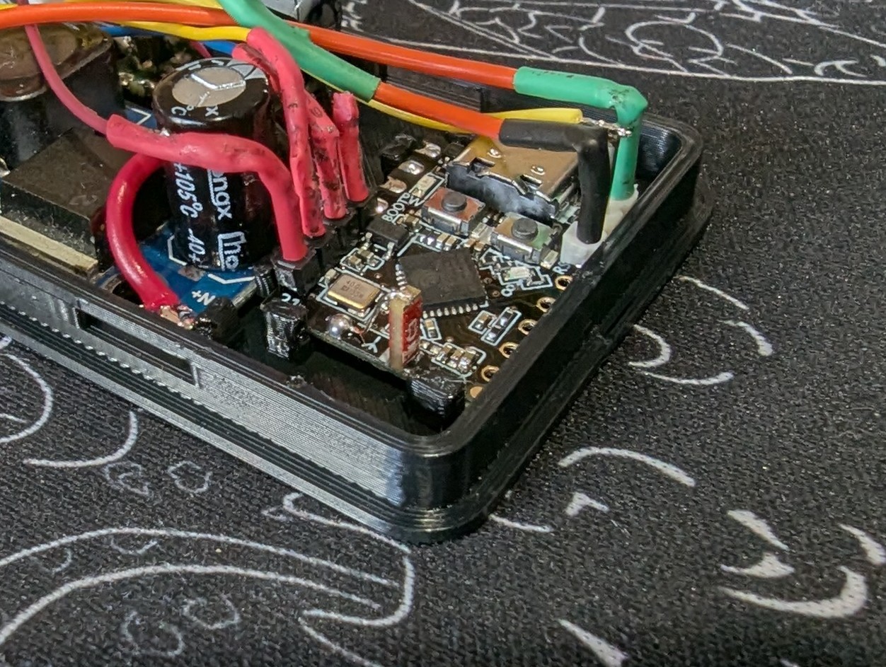
Thanks for the test you did.
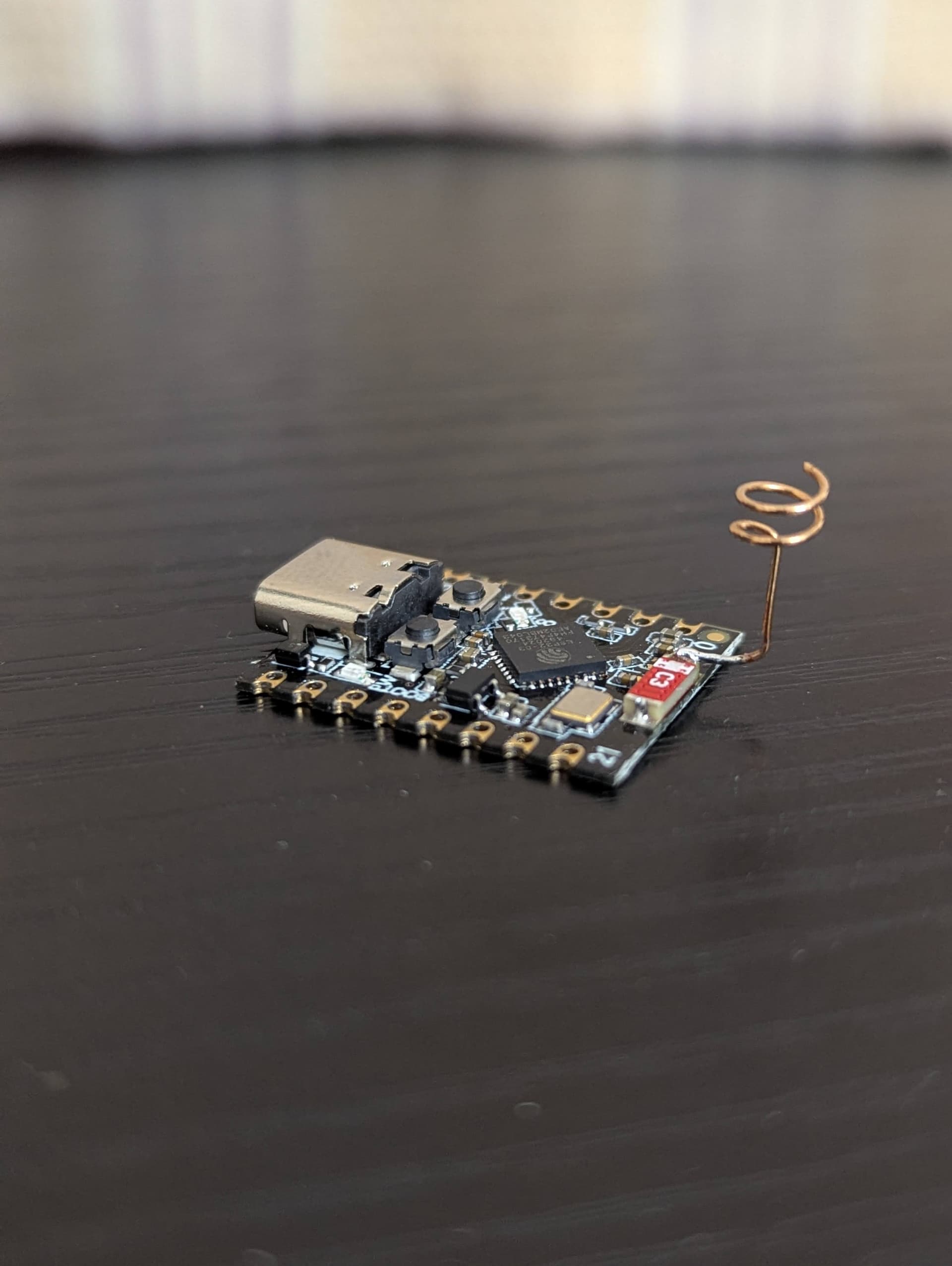
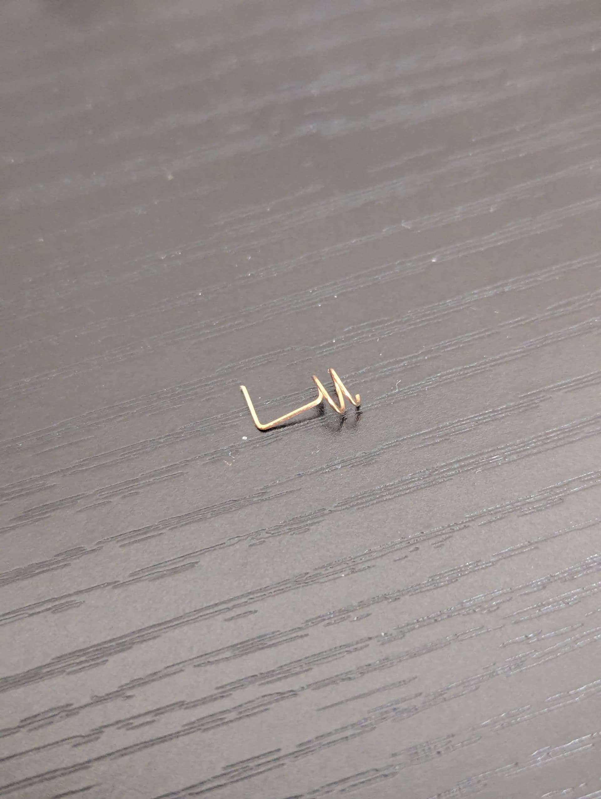
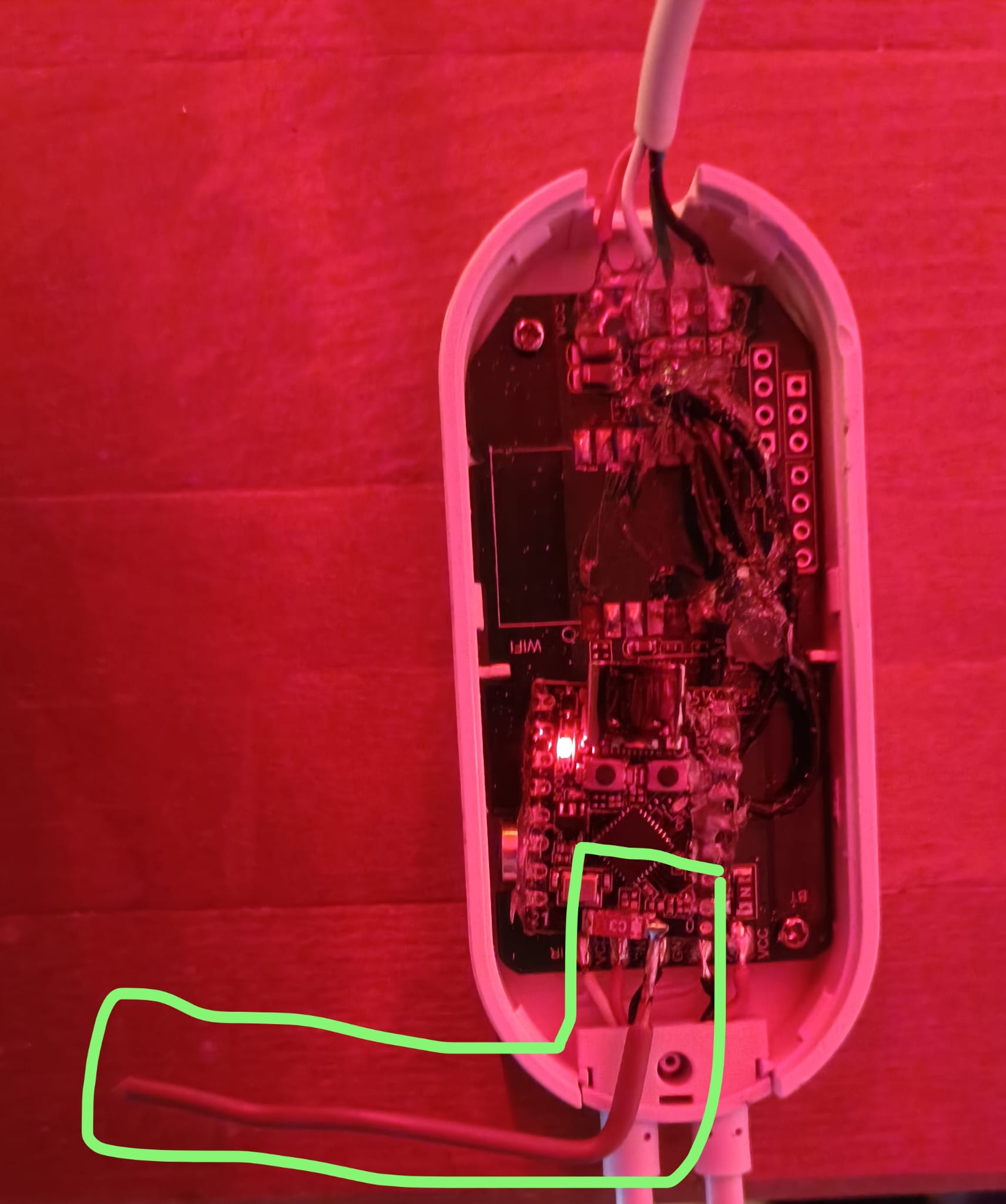
I did replace 2 faulty units’ chip antenna with solid core copper wire.
One with 0.25mm gauge and another with 0.5mm gauge. Both gave me the same amount of signal quality; and with values comparable to other ESP boards with working antenna designs.

I tried 31.25mm as well but I had no signal whatsoever.
So 62.5mm it is.
Thanks alot!
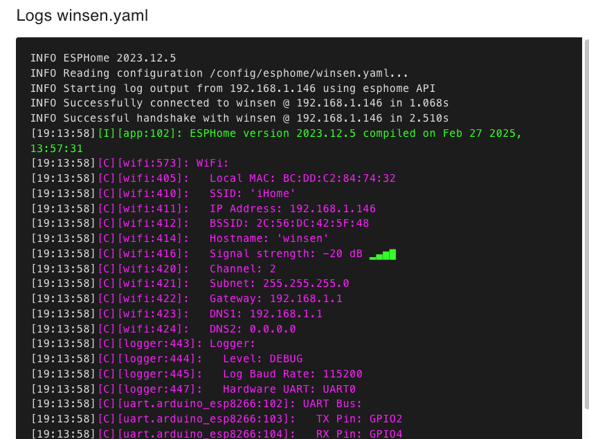
This solution only enabled the device to create an AP, and it never connected upon configuration. The struggle is not worth
 I’d instead go for Carenuity C3-Mini:
Carenuity Original C3-Mini v2.2.1 – IoT Development Board – Chipglobe
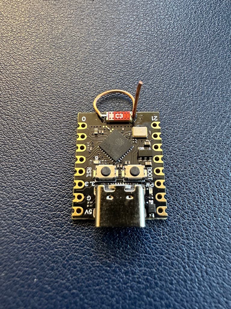
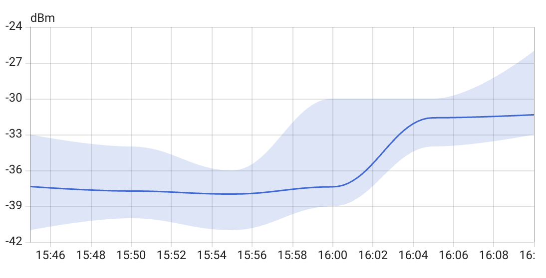
Hi all, I’ve performed a similar experiment to boost the RSSI/Power of ESP32 C3 Super Mini.
My focus was to make C3 super mini usable in a larger home and try to fit in my existing 3D printed case with minimum modifications instead of spending days on RF engineering.
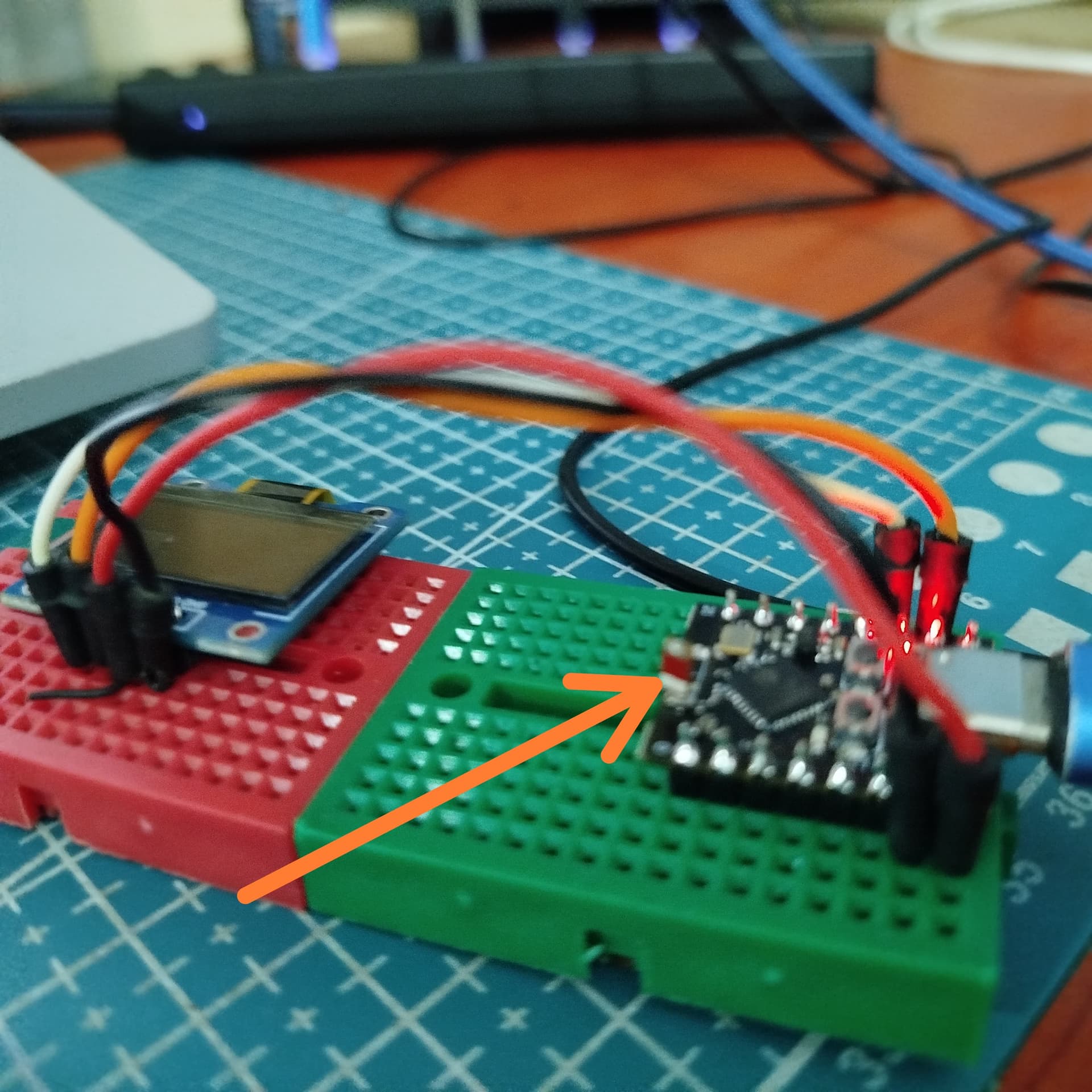
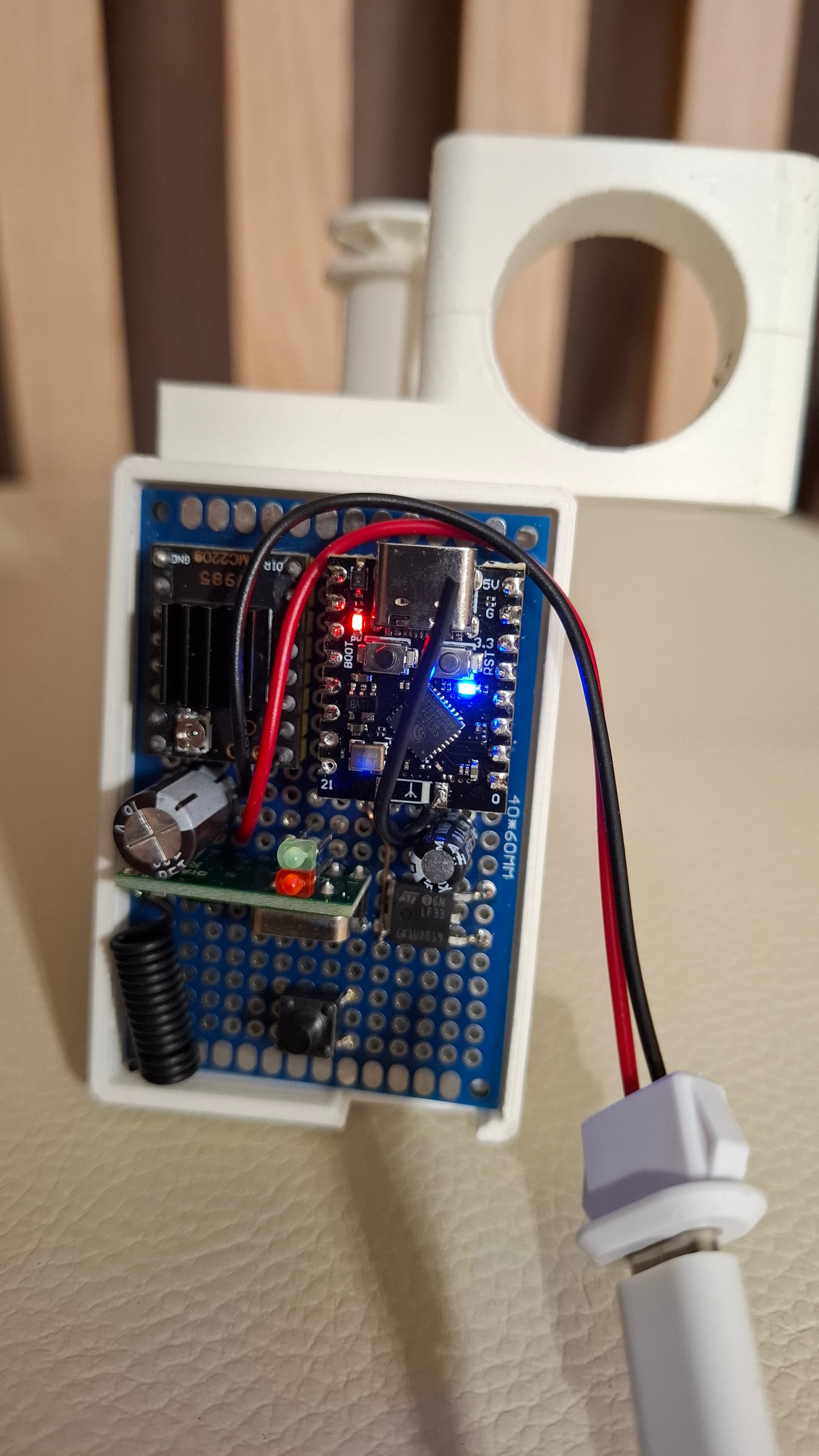
So I’ve decided to go ahead with a multi-stranded copper wire available on my shelf, with a wire length of around 61-62mm. Created a simple loop like a spring by winding it over a screw-driver. I believe that the spring like (somewhat helical?) antennas typically perform well for omni-directional radiation patterns.
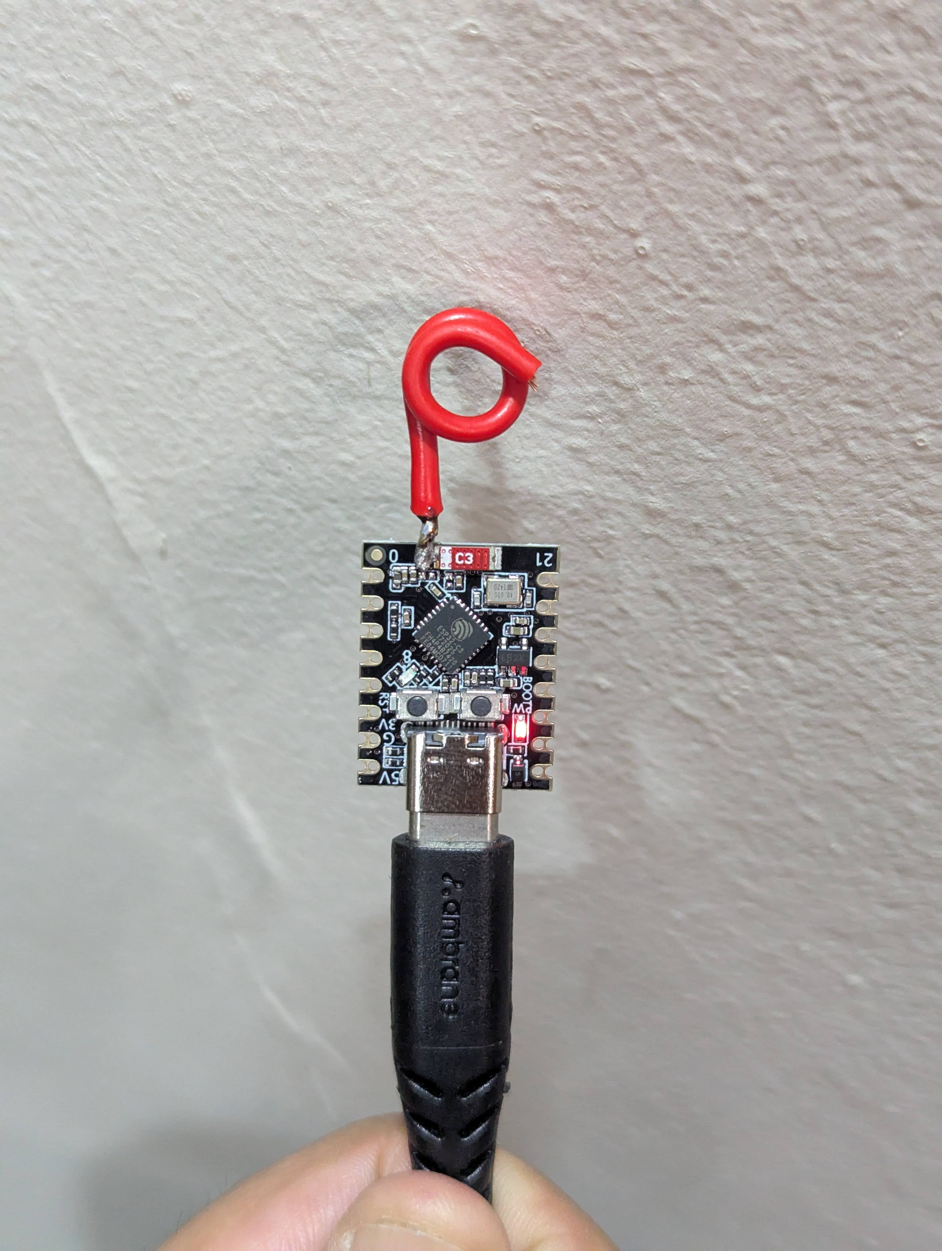
I’ve placed another ESP32 C3 Super Mini with ceramic antenna (Without any mod) next to this setup. Then I placed both these units behind my sofa before turning them on to simulate a “weak” wifi network condition.
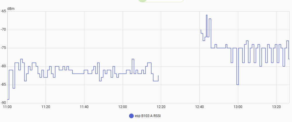
Here is the dashboard I’ve created using ESPHome that shows the result of this experiment.
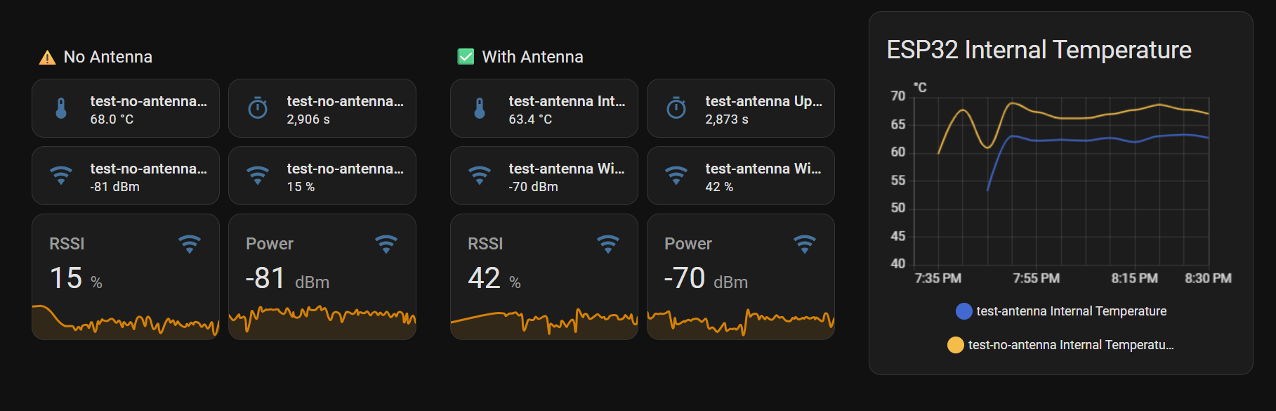
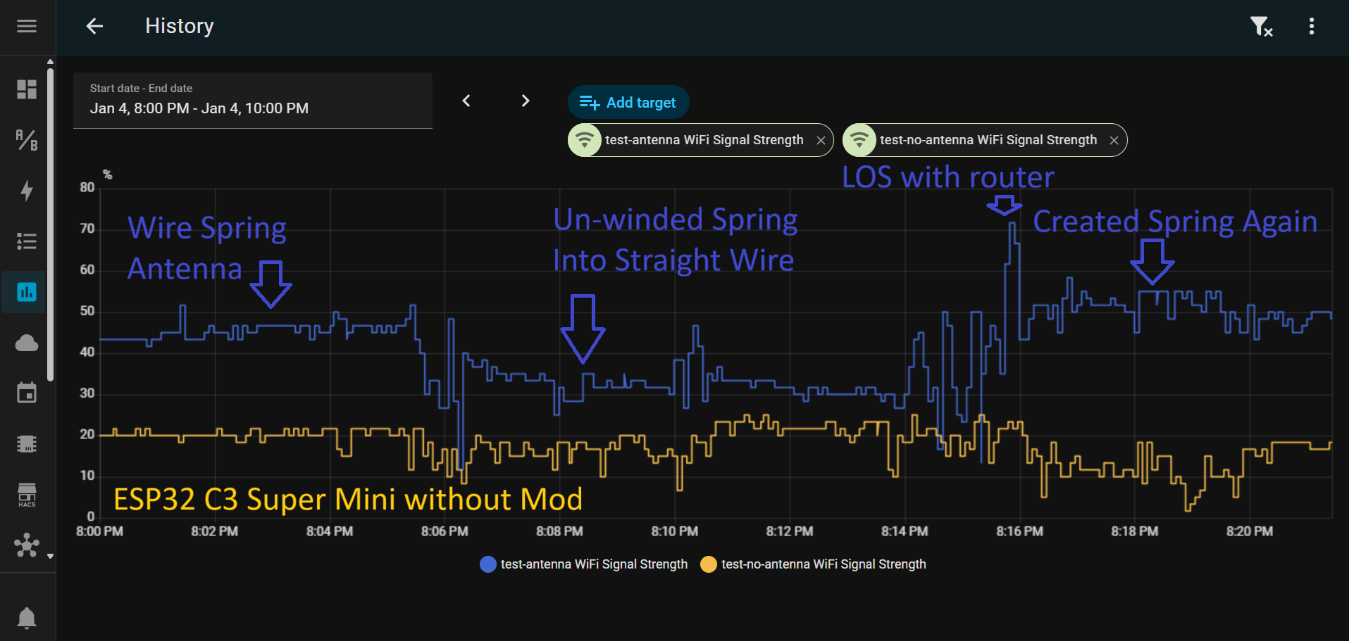
- Average RSSI and dBm power increased by ~15dBm.
- Internal chip temperature of ESP dropped by a few degrees. (Better impedeance matching and power transfer of the antenna?)
Feel free to take a look and discuss this further if needed. I’ve decided to buy a dedicated 2.4GHz antenna by AntennaHome and give it a try as well. Will update the experiment further once I try it out.
In continuation of the above experiment, this time I’ve quickly added a cheap 25-30 AWG multi-stranded Aluminium cable to another ESP32 C3 Super Mini, which was in my 3D printed case.
The below image shows change in RSSI once the modification is done. The Mod was done at 9 PM so observe the orange line before and after 9 PM (Updated every 5 mins in my actual firmware, so not as detailed as yellow/blue lines)

Seems like the antenna mod is a promising hack to enhance the poor on-board ceramic antennas on ESP32-C3 Super Mini dev kits.
Have you also tried a quarter-wavelength antenna to see if it makes much difference? Should be around 31mm in length. Asking because you’re using a half-wavelength as monopole now.
I didn’t tried 31 mm yet
But read somewhere that λ/4 requires a good ground plane which is not proper in esp32-C3 super mini. However, λ/2 don’t require a ground plane.
Maybe that’s why it works. @robertklep
My antenna knowledge is extremely limited, and if it works, it works 
I always thought that half-wavelength antennas needed to be used in a dipole setup to function optimally.
Antenna design is black magic…
Lookin at antenna @robertklep posted, I suspect that the pad where the vertical element joins to ring, is connected to PCB ground. So it’s little bit like inverted F antenna (shorted to gnd at one point)?
have sameone solder the coax cable with pcb antena to S3
I could be wrong here but, im going to assume that this isn’t the last esp32 board you ever intend to use, right? If you still plan to add additional boards/projects around the house then maybe you should rethink all of this… Rather than fiddle farting around and wasting your time trying to attach a tiny antenna to this board and likely many more future boards will require it too and my question is, why try solving it by choosing to modify this board and future boards rather than modifying your wifi signal coverage throughout your house byrectifying any weak signal areas so that you then actually fix the problem instead of fixing 1 esp32 signal by boosting it which provides no secondary benefits to other devices or even prevent the same problem from happening next time.
So, basically what im trying to say is that instead of “fixing” the esp32 by adding an antenna, you should address and fix your whole home wifi coverage by repositioning your router or adding additional Access Points to expand your coverage which would also boost the signal to those areas that you currently have an issue with.
If you don’t already have any nerwork AP’s currently or if you’re like me and like to try using components i already have before going and buying more crap than if you have a spare wifi router laying around, you can most certainly use that instead and IMO they work excellent! Most modern routers are coming with GUI’s that make converting them very simple and just takes a mouse click on most routers for Access Point Mode and it then you’re wifi coverage doubled and whether you place the router it also gives you all the free wired ports available and you use them exactly the same as how you use your primary routera ports.
It’s really so much easier and more reliable to just start out with the best board for the project such as a version of your board but with a U.Fl antenna port that only requires you to plug in whichever antenna you want. They’re overall just way better than using a little piece of wire although, whenever someone’s in a pinch the wire option is very helpful if that’s all someone has.
The problem I have with a wire like this is 1) it.s an accidental bump away from bending it over and causing a short circuit and potentially the esp32 could self-destruct from it. The 2nd thing is if you intend to use a case or enclosure then this likely wont solve the issue or it will only partially help solve it and thats only if the problem isn’t actually being caused from being inside of your case/enclosure like if it were a metal enclosure for example then adding a makeshift wire antenna won’t help 1 bit and it will require an external one.
I can also promise you that having spare boards with external antennas on hand is very helpful and its so much better when you can just go grab whatever you need, rather than ordering it and waiting for delivery.
I only needed 1 the first time i bought some and decided to just buy them as 5 packs so 5 boards and 5 antennas so that id have spares and its cheaper to buy 5 for me but, since buying extras ive come into situations where i would benefit from external antennas or i just flat out needed one and i was very happy to have extras!
Just go buy some dang boards with a U.FL plug and buy the antennas you want and then problem solved! Here’s one of them as an example.
perhaps way late to this antenna party… but if you take a look at the black ckt board ant on many esp32s, you notice the circuit track is a little snake and two ‘F’ connections are out and ground.
So you have quite literally a circuit trace that is a tiny loop from output to ground, with a pigtail trailing off into nothing down the length of the black board. All you need to do is duplicate that ratio. THAT is simple antenna gain. So the youtube vids showing a loop and a pigtail of any kind are simply dup’ing the same oem design, just larger. It’s standing wave reflection vs impedance matching. clear as mud right? (headed back under my rock). Spirals (a coil loop) will interfere magnetically (rf radiation) with itself along the stub. (will reduce output-screws with impedance matching)
Hey bud, it’s never a party untill I show up and be the pivot man in this circle jerk!! ; )
Hey bud, I’ve worked with littpe short snakes my entire life and its not the size of it, its how you operate my 2" or anything else including these antennas
Yes, im familiar with making my own antenna and using the correct wire lengths for a dipole antenna and what recreational amount ive DIY’d myself, ive not been super impressed with the results and the filtering out stray EMF or maybe they were evil spirits !!! Oh and not to mention what a pain in my Johnson it is messing with those itty-bitty tiny traces that need rerouted and soldering a tiny U.FL connector to the esp board and this is why I just prefer to buy 5 packs of boards so that ill always have extras that are ready to go and I think we can all agree that they look cleaner/professional than a DIY modified board IMO .
Hey, welcome to the club!! My Mom always said I was a constant source of dissapointment and she swears I was born with a screw loose which is similar to having a “slow screw” and all are welcome here at Jim’s Hardware Store where we offer 2 screws for 1$!! ; )