Not sure yet as I don’t have enough data to compare against. Do you have a pullup resistor on the I2C lines to get rid of the float?

Not sure yet as I don’t have enough data to compare against. Do you have a pullup resistor on the I2C lines to get rid of the float?
Hi @kimocal I have the following ADS1115 from dfrobot Gravity I2C ADS1115 16-Bit ADC Module Arduino %26 Raspberry Pi Compatible SKU DFR0553. Gravity__I2C_ADS1115_16-Bit_ADC_Module_Arduino_&_Raspberry_Pi_Compatible__SKU__DFR0553-DFRobot
I believe these have resistors built in possibly? The documentation for it does not talk about having to install resistors.
No idea. I’m still green with all the electronics stuff and learning as I go with my projects. Maybe try to see if it helps?
Hi @kimocal do you have any guide on the wiring diagram or the value of the pull up resistors to be used.

Thanks @kimocal. I will give this a shot. Once you have sufficient data could you please share your observation on any data drift with a INA219? Is your installation outdoors? Do you have a pull up resistor installed in your setup since INA 219 uses I2C bus?
This is how I wired it as well.
I used a 24V->5V USB buck converter for the ESP, that was powered from the 24V supply. That way I had common ground for both circuits.
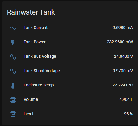
I was finally able to get the system up and in my water tank yesterday.
Here’s a 12 hour window of the current measurements:
Here’s a zoomed in view of the busy area:
Yes the installation is outdoors but I do not have a cover on it at the moment. No I do not have any pullup resistors in my setup.
Hi @kimocal thanks for posting the data trend. The data seems much more steady compared to the voltage readings that I take.
Does the change in current correspond with water going in and out of the tank and is not affected by any external factors? Are you happy with the accuracy of the readings with respect to the water level?
So far so good. I didn’t calibrate the sensor initially. As I am monitoring the water tank level with a yard stick I am also entering the current value in a spread sheet to better tune my current to water height formula. Maybe this weekend I’ll calibrate them with a wider spread of data points to tune it more. For now it’s working though.
The only external factor I can think of would be the air tube that the TL316 uses and making sure it doesn’t have wind blowing on it to affect the relative pressure compensation.
My sensor termination and all the electronics ie. power supply, nodemcu etc are located in an ip67 enclosure. That is where I have my temp probe.
My voltage readings fluctuates with the temp. I have a spare ina219 I will wire that up this weekend to see if the readings are affected.
I installed a system over the weekend using the method in the other thread, sonic sensor, so far working pretty well.
Definitely a few spikes there that I would assume are from condensation which appears to be the big issue with the sonic sensors.
This thread really seems to be about using pressure sensors. I see that people are adding additional voltage or current sensor hardware, one of the pressure sensors linked above looks to output RS485, curious why no one has gone that route? Looks like you’d need something like a MAX485 to read it in an ESP / Arduino device anyway, but feels like reading digital data might be easier?
So I connected up my INA219 breakout board to my throw in level sensor and I have noticed the fluctuation with temperature is almost non existent but the downside is with INA219 the accuracy is approx 2% (for me that’s ~100L) compared with the ADS1115 of 0.15%. Is there any way of increasing the accuracy of the INA219, replace the shunt resistor possibly?
From what I’ve been able to figure out, replacing the shunt will not help much.
You should check if you have an A or B version of the INA219. The B version has higher accuracy and precision.
Also - did you configure “max current” to 400mA? It defaults to 3.2A and that will give you a resolution of 0.8mA. Going to 400mA gives you a resolution of 0.1mA.
Hi @aherbjornsen thanks for the quick response. I have the adafruit INA219 B version. Looking through the documentation it says you can expect a 1.5% accuracy with the B version. So I guess I am not far of it. I have max current set at 400mA.
i use the 0-10v sensor with shelly uni, works perfectly
How do you have your hardware all set up?
Like so

I almost went that route after seeing that video previously. What is the accuracy of your setup?
I did not realise you can get a TL36 level sensor with a voltage output. Do you know if the readings drift with temperature if the storage tank is located outdoors?


