ESPHome water level sensor

One additional project is to measure water level in tank (and switch either well pump or pump in tank depending on whether there is water or no). Originally, I went for JSN-SR04T ( https://www.aliexpress.com/item/1005001431443682.html?spm=a2g0o.order_list.order_list_main.62.603e1802T3HPNJ ), however I was not able to get it to measure precisely, not to mention longer distances (it is advertised as up to 4m, I was not able to get it to measure above 2m).
Anyway, I purchased VL53L1X TOF400C ( https://www.aliexpress.com/item/1005003614683022.html?spm=a2g0o.order_list.order_list_main.50.603e1802T3HPNJ ). As seen in the picture, it does require some extra work to make it waterproof, but that should not be a big deal.
Since it is not natively supported by ESPHome (VL53L0X is), it took a moment to gather the right resources. I am using Wemos D1 mini. Wiring is relatively simple - sensor is powered by 3,3V (from wemos), GND, and SDA and SCL (see below config).

yaml for the device:

substitutions:
  devicename: laser-distance

esphome:
  name: '${devicename}'
  includes:
    - tof_vl53l1x.h
  libraries:
    - "Wire"
    - "VL53L1x"

esp8266:
  board: esp01_1m

# Enable logging
logger:

# Enable Home Assistant API
api:
  encryption:
    key: "xxx"

ota:
  password: "xxx"

wifi:
  ssid: !secret wifi_ssid
  password: !secret wifi_password

  # Enable fallback hotspot (captive portal) in case wifi connection fails
  ap:
    ssid: "Laser-Distance Fallback Hotspot"
    password: "xxx"

captive_portal:

i2c:
  sda: GPIO4
  scl: GPIO5
  scan: false
  frequency: 400kHz

sensor:
- platform: custom
  lambda: |-
    auto my_VL53L1X_sensor = new VL53L1XCustomSensor();
    my_VL53L1X_sensor->set_update_interval(2000); // define update interval
    App.register_component(my_VL53L1X_sensor);
    return {my_VL53L1X_sensor};
  sensors:
    name: "Distance"
    accuracy_decimals: 0
    unit_of_measurement: "cm"
    id: distance
    filters:
      - lambda: return x/10 ;
      - median:
          window_size: 15
          send_every: 15
          send_first_at: 15

- platform: template
  name: "Filled Tank %"
  lambda: return id(distance).state;
  unit_of_measurement: "%"
  accuracy_decimals: 0
  filters:
    - calibrate_linear:
        - 1 -> 100
        - 80 -> 0

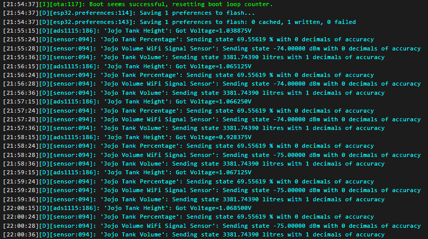
As seen, I convert measurement to cm instead of mm. In addition, template sensor is to get tank % filled. It requires setting limit values accordingly.
In order to compile, put additional file next to yaml for the device called tof_vl53l1x.h with following content:

#include "esphome.h"

#include <Wire.h>
#include <VL53L1X.h>


class VL53L1XCustomSensor : public PollingComponent, public Sensor {

 private:
  VL53L1X tof_sensor;

 public:
  // constructor
  VL53L1XCustomSensor() : PollingComponent(15000) {} // polling every 15s

  void setup() override {
    // This will be called by App.setup()
    Wire.begin();
    Wire.setClock(400000); // use 400 kHz I2C

    tof_sensor.setTimeout(500);
    tof_sensor.setAddress(0x29);
    if (!tof_sensor.init()) {
      ESP_LOGE("VL53L1X custom sensor", "Failed to detect and initialize sensor!");
      return;
    }

    tof_sensor.setDistanceMode(VL53L1X::Long);
    tof_sensor.setMeasurementTimingBudget(250000);	// 1000us = 1ms

    ESP_LOGI("VL53L1X custom sensor", "initialised");

    //tof_sensor.startContinuous(250);	// ms
  }

  void update() override {
    //uint16_t distance_mm = tof_sensor.read(false);
    uint16_t distance_mm = tof_sensor.readSingle();
    
    if (!tof_sensor.timeoutOccurred()) {
      publish_state(distance_mm);
    } else {
      ESP_LOGE("VL53L1X custom sensor", "Timeout during read().");
    }
  }
};

I must say that after few weeks of using the sensor, I am very pleased with stability and overall reporting.
For instance, here are 10-day measurements. Critical boundary is around 1.2m, so at least I can be notified when the level hit values near that, in order to take respective actions.

Hi all,

I have been using stainless pressure sensor 4-20mA for >3-4 years with very stable results via i2c and ADS1115.

The difference maybe that I have been using this: NCD.io board which includes INA196 and voltage up to 16V.

Admittedly not super cheap at $50 but converts the 4-20mA easily into i2c, along with up the voltage to 16V grounded to get pressure sensor working, along with shunt current.

Connection really couldnā€™t be easier:

i2c: SCL, SDA, 5v, GND (NB is 5V) and then pressure sensor black/red connected to other side.

Read the i2c result on address - varies from 6124 to 32125 depending on pressureā€¦

Hi all,
Iā€™m wondering if someone smarter that I can assist me.

Due to frequent water outages in our area, we initially installed 1 x 2400l tank and I installed a submersible gravity sensor into it - with the help of others here, itā€™s been working great!

Weā€™ve now had to install a second 2400l tank - both tanks are connected to one another at the bottom of the tanks via a pipe and their levels remain the same. Both are identical in shape and size, on a flat surface & next to one another (Ā± 0.5m apart).

I was wondering how I could go about measuring the total volume in both tanksā€¦
Would I need to purchase a second submersible sensor or is there some math that I could do to multiply the values.

This is what Iā€™ve tried and the results have been less than favourable with lots of fluctuations:

captive_portal:

i2c:
  sda: GPIO21
  scl: GPIO22
  scan: true
  id: bus_a

ads1115:
 address: 0x48
 i2c_id: bus_a
 continuous_mode: off
       
sensor:
- name: Jojo Tank Height
  id: tank_height
  platform: ads1115
  multiplexer: 'A0_GND'
  update_interval: 60s
  gain: 4.096
  unit_of_measurement: "metres"
  icon: "mdi:gauge"
#  accuracy_decimals: 3


  filters:

  - median:
     window_size: 200
     send_every: 10
     send_first_at: 4    


  - calibrate_linear:

    - 0.480 -> 0
    - 0.920 -> 1.550
       
- platform: template
  name: Jojo Tank Volume
  id: tank_volume
  unit_of_measurement: "litres"
  lambda: |-
    return 2 * 3.14159265 * 0.71 * 0.71 * id(tank_height).state * 1000;

- platform: template
  name: Jojo Tank Percentage
  id: tank_percentage
  unit_of_measurement: "%"
  accuracy_decimals: 0
  lambda: |-
    return (id(tank_height).state) / 1.550 * 100;
  

- platform: wifi_signal
  name: "Jojo Volume WiFi Signal Sensor"
  update_interval: 60s

switch:
  - platform: restart
    name: tankvolume

The voltage seems to be very inconsistent and erratic and thus it seems like itā€™s impossible to calibrate.

Not sure if thereā€™s a solution to this or if anyone can kindly assist :slight_smile:

Hello @mrmuttley I think you have two questions?

One tank Volume
Ļ€Ć—rƗr x height

Two tank volume
2 x Ļ€Ć—rƗr x height

Height for both is derived from your existing sensor as you have already set up the depth of the tank through linear filter. You would now set up a template sensor and create a lambada with the formula in it.

I had to do the same BUT my cylinder water tank is on its side and therefore the maths is a pig!

Did you get this problem after installing the second tank? There is no reason I can see why there should be a difference. Your sensor is a throw in pressure sensor. It only knows the height of the water above it.

1 Like

Thanks - I tried to do this as per the code aboveā€¦ would you mind having a look to see if it makes sense?

Problem only started after the second tank was added and updated the code to multiply the total by 2.
Was thinking of perhaps upping the voltage on the sensor but not sure it this would make any difference.

Any further input would greatly be appreciated!

Hi all,

Is anyone able to kindly assist me with adding in filters to my setup.
Iā€™m currently getting values that are greater than the max height, max volume and greater than for 100% for tank percentage.

Iā€™d like to display the last min/max set values and not a NAN value when filtering.

Max volume of both tanks is 4860 Liters
Max height is 1.535 Meters
and Max percentage should ignore anything above 100%

i2c:
  sda: GPIO21
  scl: GPIO22
  scan: true
  id: bus_a

ads1115:
 address: 0x48
 i2c_id: bus_a
 continuous_mode: off
       
sensor:
- name: Jojo Tank Height
  id: tank_height
  platform: ads1115
  multiplexer: 'A0_GND'
  update_interval: 60s
  gain: 4.096
  unit_of_measurement: "metres"
  icon: "mdi:gauge"
  accuracy_decimals: 3


  filters:

  - median:
     window_size: 200
     send_every: 10
     send_first_at: 4    


  - calibrate_linear:

    - 0.445 -> 0
    - 1.025 -> 1.535
       
- platform: template
  name: Jojo Tank Volume
  id: tank_volume
  unit_of_measurement: "litres"
  lambda: |-
    return 2 * 3.14159265 * 0.71 * 0.71 * id(tank_height).state * 1000;

- platform: template
  name: Jojo Tank Percentage
  id: tank_percentage
  unit_of_measurement: "%"
  accuracy_decimals: 0
  lambda: |-
    return (id(tank_height).state) / 1.535 * 100;
  

- platform: wifi_signal
  name: "Jojo Volume WiFi Signal Sensor"
  update_interval: 60s

switch:
  - platform: restart
    name: tankvolume

Thanks in advance :slight_smile:

Hello @mrmuttley, first thing is to check what the voltage is when the tank is at the maximum height i.e. full. You may have already done that but it clearly has moved. Easy thing to do is # out the three lines of calibrate _linear, reflash and then reread the new voltage from the logs. Remove the #ā€™s and reenter the calibrate line with the new voltage number i.e. not 1.025

Just need to write some if statement for volume and percentages if you find the base voltage is still wondering around. I can help

Thanks so much for your help with thisā€¦

Iā€™ve tried re-calibrating and re-measuring the actual height of the water so many times that I feel like Iā€™m trying to hit a moving target. Iā€™ve even taken the probe out to get a new 0 voltage.

Thereā€™s a buck/dc-dc converter installed for both the probe and ESP32 to try keep things stable as suggested by others above.
Iā€™m wondering if perhaps the probe or the 4-20mA to voltage converter is faultyā€¦

For a few days the voltage was 1.025 and now itā€™s 1.067ā€¦

Hence the reason why Iā€™d like to try filter out the variables and set a min and maxā€¦
Thanks for the help and input- any additional help would greatly be appreciated!

Hey community,

I wanted to measure my stormwater soak-drain changes (rises quickly, falls slowly, does it overflow?), and solve a rain-water tank problem measurement for a relative.

Journey

Thereā€™s a dearth of good water/liquid depth sensors that are pre-integrated into esphome, and certainly none pre-packaged thatā€™ll measure levels that I could find. I think this is mainly because itā€™s a hard problem to solve in a general sense (how deep, which liquid, etc), but also because the best sensors out there for this purpose are non-trivial to connect to (powered, analog).

I chose the 4-20mA variant sensor immersion sensors after reading way too much here and elsewhere (ultrasonic dead zones, waterproofness, ripples etc and trying to solve for both my use cases). On my research journey I found integrations for current sensors directly onto esp32 boards that required discrete circuitry, but that plus getting the (recommended for this sensor) 24v near the esp32 didnā€™t seem like a great idea. There are also super-cheap (like $5) industrial sensor->RS-485modbus modules though that can take 2(+) sensor inputs, and are designed to be permanently installed and robust to mistreatment/lightning/etc. So I took that option.

Then thereā€™s RS-485 which has been around forever but Iā€™d not appreciated it as useful for IoT until now. There also esp32 integrations/sub-boards for RS-485. And then thereā€™s the Lilygo T-CAN485 which has an nicely isolated RS-485 interface on it already, and means I didnā€™t need another board. They do other boards with RS-485 too, but every single one is different.

For this project I decided that the water sensor could be remote, and the esp32 etc could be further away from the water, and then just running 12v to it would be easiest.

Materials

(no affiliate links, but links might be country-dependent)

There are many liquid sensors of this submersible kind. Not all are equal (reports are that some rust) and I believe this store is the OEM and not a re-reseller. These sensors are quite a bit bigger and more hefty than they look in the photos. Ensure the cable length is long enough as itā€™s got a pressure-equalisation tube inside it that needs to be kept out of the water(discussed above), I guess they can be cut down (but I didnā€™t) but extending could be problematic. They want 24v but will apparently run on 12v.

Pictures


Testing in my water bottle.


Sensor, 18650 for size reference :slight_smile: Sensor is quite heavy.


Installed, working, with ferrules even. Cable management could be betterā€¦

esphome configuration

Modbus configuration of the T-CAN485 board is a little annoying and was undocumented outside of the Arduino examples. It works though, just needs some pins flipped high. Feedback welcomeā€¦

Full yaml here

Got the RGB LED working properly too.

Results

It verks!

And installed and on a dashboard.

Final Thoughts

I like using these off-the-shelf components. Theyā€™re robust although not that space efficient. I am thinking about why I donā€™t have an RS-485/modbus bus loop around my house now too. I have no real-world experience with it yet but now I see why there is an RS-485 version of my weather station (Ecowitt), and it looks like I could loop in my aircon and solar inverter too.

The industrial 4-20mA current sensor approach is something Iā€™d do again for remote sensors because after the ā€œwhy did they make it so complicated?ā€ thoughts subsided I realised that this range stays ~static regardless of the length of the wire to the sensor (unlike say 0-5v), and probably other good reasons too. Itā€™s clearly not a low-power (uA) consumption approach though, so you do need a stable power source. Once 4-20ma sensor integration is solved for one type we can apply this to other types of sensor like this as well as wellā€¦

The ā€œ12 bitā€ RS-485 sensor converter is using less than 12 bits because it uses 2621 values for the 4-20mA range of the sensor, which is not 4096 (12 bits). Still enough values for sufficient precision for my purposes. Docs went through Google Translate fine. Canā€™t beat the price, and thereā€™s space for another sensor.

The sensor is (a few days in) awesome. Came well packaged, calibrated to the values engraved, and just works. It will take some years to prove them out completely, but it looks like the real thing. I could have ordered the RS-485 version (and avoided a box), but I these are more common and replaceable. Seems ~stable across temp and barometric changes at least within 2mm change.

The case probably needs a vent as so the barometric compensation works properly, but itā€™s not wildly varying (my XT60 hole may be providing this). Iā€™ve ordered some cable glands with ventsā€¦which are a thing. TIL.

2 Likes

that is about 4% variability ā€¦ I am getting 0.45% ā€¦ what is the rated working depth you purchased? I would have to rerun the numbers when we get to summer and tank lower. How about following:

    filters:
      - lambda: if (x > 1.067) { return 1.067; } else { return x; } 
      - calibrate_linear:
          - 0.028 -> 0
          - 1.067 -> 1.535
      - sliding_window_moving_average:
          window_size: 200
          send_every: 10

I update every second and perhaps with your longer average period that may smooth things out. Otherwise 4% is not the worst thing in the world.

Also you can use the following filter which will ignore any data less than 4% of the last number. You could use combination of filters remembering the order of the filters is important.
- delta: 4%

1 Like

Thanks so much!

Iā€™ve tried this and itā€™s giving me the 100% value as expected.

Still think something is up with my setup as I re-calibrated everything yesterday and the voltages seem to be stable as per the calibration, then they start to mysteriously increaseā€¦

This is the sensor which Iā€™ve been using.
Wondering if I should try buying a new DF Robot Current to Voltage Converter 4-20mA and seeing if this helps - itā€™s cheaper than buying the whole kitā€¦

The sensor is sitting at the bottom of the tank in an upright position, should I perhaps allow it to float/be suspended mid tank?

Would an increase in temperature possibly cause this?
If so, is there a way to compensate for thisā€¦
The temps here have been hovering around 30degrees celcius

Any other suggestions would greatly helpā€¦

The raw voltage increases as reported by the ADC? (Not just the output of the filter)

If you have a reasonable meter then do some readings to see if itā€™s the sensor (so measure the current) or the conversion (voltage on output of the current to voltage) and try and establish which part shows an increase? ie if neither of those itā€™s the adc. If youā€™re considering changing the converter then why not get the mA to i2c converter(also DFRobot, ā€œI2C 4-20mA DAC Module (Arduino Compatible)ā€ and collapse one source of error?

Iā€™ve been cycling from 20 to 40C ambient temps on my similar sensor with very little error, and I wouldnā€™t think that your quantity of water is changing temp that fast anyway? I did see some errors with barometric pressure changes, maybe overlay those graphs too to see if you spot a trend related to that?

1 Like

Hi,
Mr Muttley, I was having simlar issues with the 4-20mA variety. I changed esp boards and added in ADC boards -the list of pieces kept growing.
Then I found Lars Klint posted about a Shelly uni and a sensor that outputs voltage.
I flashed out on more gear and it has been installed for 6 months or more now and I have no issues with the sensor and readings. I am contemplating my power issue (currently a solar panel into a 12v car battery) this at least becomes active once per day and takes my readings required.

1 Like

If you want put a temp sensor in the water tank and then overlay over with your chart above. I would take a week chart to see if it is linked with air pressure and temperatures movements.

Can you remind me how long is the run between the ADS1115 and the current to voltage unit? And can you confirm the rated working pressure range for the pressure sensor.

I do not use current to voltage but ordered the 0-5v variety and have it running over 25 metres straight to the ADS1115. I do get variations but not that much ā€¦

You have made me look at my history and I realise my tank has been flooding!!! I am 3.8m inground and water table has been so high that the tank has been gone past the overflow level and filled up to top of turret and the surrounded lawn is now sea level!! I have now a notification from my tank pressure sensor to tell when the garden is flooded!!!

2 Likes

Hi all,

Thanks so much for the very useful input - got me fiddling and fiddling and fiddling yet results came back with no positive results.

Iā€™ve now ordered a new current to voltage module and a new ADS1115.
In addition to this, Iā€™ve ordered a Shelly Uni (first time trying one of these).

If the new current to voltage module and new ADS1115 donā€™t make a meaningful difference, Iā€™m going to try using the Shelly Uni plus the current to voltage module with my existing pressure sensor.

Current setup:

Shelly proposal:

Not sure if the Shelly Uni idea will work, if not, Iā€™ll order a 0-10V submersible sensorā€¦

Any input as always is appreciated!

What youā€™ve got should work. Why not move all of your power and circuitry over to the left-hand-side and run the sensor over the wires you have? This is the beauty of 4-20mA sensors, there is no voltage drop issue because youā€™re not measuring that.

Then you can keep a common earth for everything too, 24v power supply to both regulators, avoid any loss or noise currently being induced in the 0-5v long(?) wire run, and potentially wrap it up in one tidy box.

Then if youā€™re still seeing oddness get back to basics and measure some baseline values (of the sensor, of the ADC output) with a meter, or at least before esphome filters distort them with filtering and fitting. Maybe turning up the debug level will be enough to see that?

1 Like

No need for extra ADS1115 + Current-to-Voltage converter with an ESP32.
Just use either an INA219 or INA226 DC current sensor.
I have been using an INA226 and the same type of transducer (4-20mA, range 0-5m) for exactly your application scenario for about a year now without any problems. Flawless operation, measured value tolerance < 1 cm. Put the transducer on the high side of the INA

- platform: ina226
    address: 0x40
    shunt_resistance: 0.1 ohm
    current:
      name: "INA226 Current"
      id: raw_current
      filters:
        - multiply: 1000  # conversion to mA
      unit_of_measurement: mA
    bus_voltage:
      name: "INA226 Bus Voltage"
    shunt_voltage:
      name: "INA226 Shunt Voltage"
      filters:
        - multiply: 1000  # conversion to mV
      unit_of_measurement: mV
    max_current: 50mA
    update_interval: 10s

  - platform: template
    name: Water gauge
    unit_of_measurement: cm
    accuracy_decimals: 0
    update_interval: 30s
    filters:
      - sliding_window_moving_average:
          window_size: 10
          send_every: 5
    lambda: |-
      auto current = id(raw_current).state;
      return 100 * current / 5;  // Sensor: 4-20 mA, factor 100 to cm convert, range=5m
2 Likes

Thanks for the inputā€¦
After a few days of fiddling, I decided to test the whole system with a new ESP32 and a new ADS1115 plus having 1 power supplyā€¦
Things seem to be much more stable but Iā€™m still not yet entirely confident in my current "excuse the pun :smiley: " setup.

My current setup as seen below, I tried using the DFRobot ADS1115 which I had lying around but been struggling to find meaningful info on this device - still not sure if Iā€™ve wired it correctly by connecting the positive from the current to voltage module to the positive on the A0 pinā€¦ Any ideas?

captive_portal:

i2c:
  sda: GPIO21
  scl: GPIO22
  scan: true
  id: bus_a

ads1115:
  - address: 0x48
    id: ads1115_48
    i2c_id: bus_a

sensor:
- name: Jojo Tank Height Gravity ADS1115
  id: jojo_tank_voltage_gravity_ADS1115
  ads1115_id: ads1115_48
  multiplexer: 'A0_GND'
  update_interval: 5s  
  gain: 4.096
  platform: ads1115
  unit_of_measurement: "metres"
  icon: "mdi:gauge"  
  accuracy_decimals: 3
  filters:
    - sliding_window_moving_average:
       window_size: 200
       send_every: 10
       send_first_at: 10

#    - median:
#        window_size: 200
#        send_every: 30
#        send_first_at: 30

    - calibrate_linear:
      - 0.210 -> 0
      - 0.800 -> 1.545
       
- platform: template
  name: Jojo Tank Volume
  id: tank_volume
  unit_of_measurement: "litres"
  lambda: |-
    return 2 * 3.14159265 * 0.71 * 0.71 * id(jojo_tank_voltage_gravity_ADS1115).state * 1000;

- platform: template
  name: Jojo Tank Percentage
  id: tank_percentage
  unit_of_measurement: "%"
  accuracy_decimals: 0
  lambda: |-
    return (id(jojo_tank_voltage_gravity_ADS1115).state) / 1.545 * 100;
  

- platform: wifi_signal
  name: "Jojo Volume WiFi Signal Sensor"
  update_interval: 60s

switch:
  - platform: restart
    name: tankvolume

1 Like

Thanks for your input on my dilemma - would you mind sharing a wiring diagram?