Geiger counter with HA integration?

I’ve never used ESPHome so I can’t say how that would need to be set up.

However, if you replace the Geiger counter with a button, momentary switch connected to VCC (or just a wire you can tap), do you get any counts when you press the button or tap the wire?

Did you guys see my post about a Geiger counter?
https://www.connectix.nl/connecting-a-geiger-counter-to-home-assistant/

I also can provide a ready-to-use example on integration of the GGreg20_V3 (SBM20 tube) ionizing radiation detector module into the HA using ESPHome under ESP8266 or ESP32.
https://github.com/iotdevicesdev/ggreg20-v3-homeassistant-esphome-example
It is also simple to convert those sample yaml-code to support any simmilar tubes tunning a convertion coef.
BR,

1 Like

There’s another version on sale through Banggood now - one with an oled display. Has anybody integrated this with HA?

i bought one, needed some mods to get it working. put esphome on it. works a treat.

4 Likes

that is just some grafics with the duration of the data?

the device puts out CPM. The Geiger tube has a specific micro Sieverts per hour calibration depending on the type of tube. Just added ESP32 and ESP home to count and transmit the data.

Here is my ESPH code.


esphome:
  name: esp-geiger01

esp32:
  board: esp32dev
  framework:
    type: arduino

# Enable logging
logger: 
  #level: VERY_VERBOSE
  
# #Enable Home Assistant API
api:
 password: "getyourown"
 encryption:
  key: "getyourown="

ota:
  password: "getyourown"

wifi:
  ssid: urssid
  password: "getyourown"
  domain: .urdomain.local
  
# #Optional manual IP
  manual_ip:
    static_ip: x.x.x.x
    gateway: x.x.x.x
    subnet: 255.255.255.0
    dns1: x.x.x.x
    
switch:
  - platform: restart
    name: "esp-geiger01 Restart"

sensor:
  - platform: uptime
    name: "esp-geiger01 Uptime"
    update_interval: 60s
    
  - platform: wifi_signal
    name: "esp-geiger01 Wi-Fi Signal"
    update_interval: 60s

  - platform: pulse_counter
    pin: GPIO36
    name: "esp-geiger01 geiger counter CPM" 
    id: "geiger_counter"
    update_interval: 60s
    unit_of_measurement: 'CPM'
    on_raw_value:
      - sensor.template.publish:
          id: radiation_level
          state: !lambda 'return x *0.0081;'
# # this was what I got for my data sheet and it matched reasonably well with the background data that I have.  Many people are using other values.
          
  - platform: template
    name: "esp-geiger01 Radiation Level"
    id: "radiation_level"
    unit_of_measurement: 'µSv/h'
    update_interval: 60s
    icon: mdi:radioactive
    accuracy_decimals: 5
    
  - platform: dht
    update_interval: 10s
    pin: GPIO16
    model: DHT11
    temperature:
     name: "esp-geiger01 Temperature"
     unit_of_measurement: "°C" 
     filters:
      offset: 0
     
    humidity:
      name: "esp-geiger01 Humidity"
      filters:
       offset: 10
    
binary_sensor:
  - platform: template
    device_class: safety
    name: "esp-geiger01 Radiation Warning"
    # # This doesn't necessarily represent a "dangerous" count, but one that is abnormally high
    lambda: |-
      if (id(geiger_counter).state > 100) {
        // High Count.
        return true;
      } else {
        // Normal Count.
        return false;
      }

text_sensor:
  - platform: version
    name: "esp-geiger01  ESPHome version"

time:
  - platform: homeassistant
    id: homeassistant_time

1 Like

I know that my question is about the graphs… I know how to do them with time but…. How do you do the top limit? I assume that it’s the security point isn’t it?

type: custom:mini-graph-card
name: Radiation Level - 1hr
icon: mdi:radioactive
hours_to_show: 1
points_per_hour: 60
line_width: 1
entities:
  - entity: sensor.esp_geiger01_radiation_level
    name: µSv/h
    units: µSv/h
    line_width: 5
    color: green
    show_state: true
    show_line: true
    show_fill: true
    show_points: true
  - entity: sensor.virtual_sensor_020_usv
    name: 020 µSv
    units: µSv
    line_width: 5
    color: orange
    show_state: false
    show_legend: false
    show_line: true
    show_fill: false
    show_points: false

2022-07-19_192009 - Copy

Create Virtual sensors in your HA configuration.yaml and add them to the graph

#Virtual CPM for Graphing
  - platform: virtual
    name: 'sensor.30_CPM'
    class: measurement
    initial_value: 30
    initial_availability: true
    
#Virtual µSv for Graphing
  - platform: virtual
    name: 'sensor.020_µSv'
    class: measurement
    initial_value: 0.20
    initial_availability: true
2 Likes

I’ve posted my finished thing in the Share Your Projects area.

1 Like

Thank You!!!

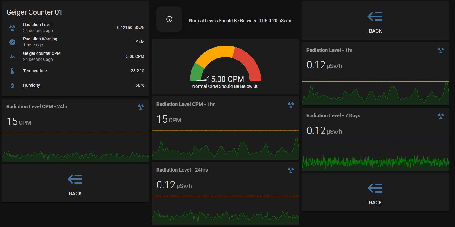
Realized I didn’t actually post my source code. It’s mostly the Brian Gauger example code with MQTT communication added.

I used an STM32 “Blue Pill” because I already had one set up on a breadboard with a W5500 module however any Arduino will work if you adjust the library used (from Ethernet_STM to Ethernet) and the pin used for attachinterrupt() . See Arduino interrupt pins.

/*************************************************************************
 * Filename: rhGeiger.ino                                                *
 * Author:   Brian K. Gauger (based loosely on code by Alex Boguslavsky) *                                          *
 * Date:     11 Oct 2018                                                 *
 * Purpose:  Arduino code for http://rhelectronics.net v3.00 board,      *
 *           Serial Monitor version                                      *
 *                                                                       *
 * Arduino IDE version: 1.0.6                                            *
 * Executable Size: ~5.6 kbytes                                          *
 *                                                                       *
 * Copyright 2018 Brian K. Gauger                                        *
 *                                                                       *
 * Licensed under terms of Creative Commons Attribution-ShareAlike 4.0   *
 * International (CC BY-SA 4.0). You can do pretty much anything you     *
 * want with this code, provided you:                                    *
 *      a) Give me credit somewhere in the comments, and                 *
 *      b) Distribute your modified code under the same terms.           *
 *************************************************************************
 *                                                                       *
 * ===================================================================== *
 * Speaking of credit... MANY THANKS to Alex Boguslavsky for developing  *
 * the rhGeiger kit, and for the original code that inspired this!       *
 * ===================================================================== *

 *************************************************************************
 *
 * IMPORTANT NOTE:
 * ===============
 * The radiation levels reported by your Geiger Kit are APPROXIMATE only!
 * GM tubes vary greatly in terms of sensitivity to alpha, beta, and
 * gamma radiation. Some good info at:
 * https://sites.google.com/site/diygeigercounter/gm-tubes-supported
 *
 * If you need the CPM to microSievert conversion factor for GM tubes
 * OTHER than the SBM-20, this is a good place to begin looking.
 *
 * Remember, your unit is NOT calibrated to a standardized source.
 * So, take your readings with a large grain of salt substitute (a slightly
 * radioactive "check source"! A small plastic bag of KCl laid on top of my
 * SBM-20 yields about 6x background in my area. Your results will vary).
 */

 /////////////////////////////////////////////////////////
 // HARDWARE CONNECTIONS --                             //
 // A) Connect Geiger PCB INT output to Arduino pin 2.  //
 // B) Connect  Geiger PCB & Arduino grounds together.  //
 // C) Ensure C-INT (103, 0.01 uF) is soldered on the   //
 //    Geiger PCB.                                      //
 /////////////////////////////////////////////////////////

 // Averaging (logging) period in milliseconds, typically 15000-60000.   
#define AVG_PERIOD  15000
#define ONE_MINUTE  60000

// I'm using the SBM-20 Geiger-Muller (GM) tube with my kit. Conversion
// factors for other GM tubes may be found scattered throughout the Web.   

#define SBM_20

#ifdef SBM_20
#define CONV_FACTOR 0.0057   // SBM-20 counts to uSv/hr multiplier
#endif


#include <itoa.h>

//PubSubClient library for MQTT
#include <PubSubClient.h>


//ethernet related includes
#include <SPI.h>
#include <Ethernet_STM.h>							//ethernet2 for non-STM32

// Enter a MAC address and IP address for your controller below.
// The IP address will be dependent on your local network:
#if defined(WIZ550io_WITH_MACADDRESS) // Use assigned MAC address of WIZ550io
;
#else
byte mac[] = { 0xDE, 0xAD, 0xBE, 0xEF, 0xFE, 0xED };
#endif  


// Initialize the Ethernet client library

EthernetClient ethClient;

//MQTT

//MQTT sever address
#define MQTT_SERVER "192.168.1.10"  

void MQTTCallback(char* topic, byte* payload, unsigned int length);		//function prototype for MQTT callback

char const* MQTTClientName = "geiger";								//MQTT client name. Keep short, don't waste RAM
const char TelemetryTopic[] = "/geiger/tele/";					//Suffix added to board topic for telemetry heatbeat
const char CountTopic[] = "/geiger/cpm/";
const char DoseTopic[] = "/geiger/dose/";

PubSubClient MQTTClient(MQTT_SERVER, 1883, MQTTCallback, ethClient);	//pass Ethernet object to PubSubClient and create MQTT client


unsigned long counts; // # of raw GM Tube events
unsigned long cpm;				// Counts Per Minute (CPM)
unsigned int  mult;   // CPM = (counts in a given interval) * multiplier

char CountString[16];
char DoseString[16];


// Interrupt handler that counts raw events from Geiger Kit
void tube_impulse() {
	counts++;
}


void ConnectToMQTTBroker() {


	// Loop until connected to MQTT broker
	while (!MQTTClient.connected()) {
		Serial.println(F("MQTT: Attempting connection..."));

		//if connected, subscribe to the relay topics as BoardTopic/relay number
		if (MQTTClient.connect((char*)MQTTClientName)) {
			Serial.println(F("MQTT: Connected"));

		}
	}
}

void MQTTCallback(char* topic, byte* payload, unsigned int length) {
	//function called when MQTT message received

}


void setup()
{
	counts = 0;
	cpm = 0;

	// Initialize Serial communications
	Serial.begin(9600);

	Serial.println(F("Boot"));

	// start the Ethernet and obtain an address via DHCP
	Serial.println(F("Start: Ethernet..."));

	if (Ethernet.begin(mac) == 0) {
		Serial.println(F("FAIL: Ethernet: No DHCP."));

	}


	Serial.print(F("Success: Ethernet. DHCP IP: "));
	Serial.println(Ethernet.localIP());

	delay(3000);

	ConnectToMQTTBroker();							//connect to MQTT broker


	// Determine multiplier for your log period
	mult = ONE_MINUTE / AVG_PERIOD;

	pinMode(PA0, INPUT);                          // Set pin 2 up for GM tube event interrupts
	digitalWrite(PA0, HIGH);                      // Use internal pullup resistor


	//attachInterrupt(0, tube_impulse, FALLING);
	attachInterrupt(digitalPinToInterrupt(PA0), tube_impulse, FALLING);

	Serial.print(F("First reading in "));
	Serial.print(AVG_PERIOD / 1000);
	Serial.println(F(" sec..."));
	
}

void loop()
{

	//reconnect if connection is lost
	if (!MQTTClient.connected()) { ConnectToMQTTBroker(); }

	MQTTClient.loop();									//maintain the MQTT connection

	// Elapsed time stuff
	static unsigned long then;
	unsigned long now = millis();

	// Approx radiation level in microsieverts
	double uSv;

	switch (Ethernet.maintain()) {
	case 1:
		//renewed fail
		Serial.println(F("ERROR: DHCP Renewal Failure"));
		break;

	case 2:
		//renewed success
		Serial.println(F("SUCCESS: DHCP Renew"));
		//print your local IP address:
		Serial.print(F("IP Address: "));
		Serial.println(Ethernet.localIP());
		break;

	case 3:
		//rebind fail
		Serial.println(F("ERROR: Rebind failure"));
		break;

	case 4:
		//rebind success
		Serial.println(F("SUCCESS: Rebind"));
		//print your local IP address:
		Serial.print(F("IP Address: "));
		Serial.println(Ethernet.localIP());
		break;

	default:
		//nothing happened
		break;
	}


	if (now - then > AVG_PERIOD) {
		then = now;
		if (counts) {                     // i.e., if (counts != 0)
			cpm = counts * mult;
			uSv = cpm * CONV_FACTOR;
		}
		else {
			uSv = 0;
		}
		Serial.print(F("Counts: "));
		Serial.println(counts);
		Serial.print(F("CPM: "));
		Serial.println(cpm);
		Serial.print(F("uSv/hr: "));
		Serial.println(uSv, 4);          // Display 4 decimal places
		
		//convert both numbers to cstrings for MQTT publish
		itoa(cpm, CountString, 10);
		dtostrf(uSv, 5, 5, DoseString);


		counts = 0, cpm = 0;							//reset the counts fo rnext loop
	
		Serial.print(F("MQTT Publish:"));
		Serial.print(CountTopic);
		Serial.println(CountString);
		
		Serial.print(F("MQTT Publish:"));
		Serial.print(DoseTopic);
		Serial.println(DoseString);


		MQTTClient.publish(CountTopic, CountString);					
		MQTTClient.publish(DoseTopic, DoseString);
	}
	
}


Hi. I have the CAJOE version of the Radiation detector. I calibrated it, and it powers up fine, and beeps and has VIN drop low on an oscilloscope when it clicks from background radition.

I have an Olimex ESP32-POE-ISO unit that is powered by POE (the final home of this is on my roof, and thanks to mylar coated sheathing there is no WiFi up there. I am powering the geiger counter from the Olimex 5V and GND pins, and again, works just fine. I have the VIN pin wired to GPIO36, and tested the wiring for continuity, but for the life of me, the Olimex isn’t seeing any pulses. Everything just says 0…

Here is the code in esphome that I am using:

esphome:
  name: radiation-monitor
  platform: ESP32
  board: esp32-poe


ethernet:
  type: LAN8720
  mdc_pin: GPIO23
  mdio_pin: GPIO18
  clk_mode: GPIO17_OUT
  phy_addr: 0
  power_pin: GPIO12


# Enable logging
logger:

text_sensor:
  - platform: template
    name: Uptime Human Readable
    id: uptime_human
    icon: mdi:clock-start

# Sensors with general information.
sensor:


  # Uptime sensor.
  - platform: uptime
    name: Geiger Counter Uptime
    id: uptime_sensor
    update_interval: 60s
    on_raw_value:
      then:
        - text_sensor.template.publish:
            id: uptime_human
            state: !lambda |-
              int seconds = round(id(uptime_sensor).raw_state);
              int days = seconds / (24 * 3600);
              seconds = seconds % (24 * 3600);
              int hours = seconds / 3600;
              seconds = seconds % 3600;
              int minutes = seconds /  60;
              seconds = seconds % 60;
              return (
                (days ? to_string(days) + "d " : "") +
                (hours ? to_string(hours) + "h " : "") +
                (minutes ? to_string(minutes) + "m " : "") +
                (to_string(seconds) + "s")
              ).c_str();

  - platform: pulse_counter
    pin: GPIO36
    name: "Geiger Counter"
    id: "geiger_counter"
    unit_of_measurement: 'CPM'
    on_raw_value:
      - sensor.template.publish:
          id: radiation_level
          state: !lambda 'return x / 153.8;'
  - platform: template
    name: "Radiation Level"
    id: "radiation_level"
    unit_of_measurement: 'µSv/h'
    icon: mdi:radioactive
    accuracy_decimals: 5

Any ideas as why this isn’t working? The board documentation says pin 36 is available for input and has an internal pullup: https://www.olimex.com/Products/IoT/ESP32/ESP32-POE-ISO/resources/ESP32-POE-ISO-GPIO.png

Thanks!

1 Like

There are no ideas. Everything looks correct at first glance.

ESPhome pulse counter enable pcnt by default on esp32.
You have to disable it to make the cajoe geiger working.

Try to add this line to the pulse counter definition:
use_pcnt: false

Also i had some problems with GPIO36, I have had better results with a pin without ADC.

That line doesn’t work in the pule counter definition. Where does it go?

I have tried GPIO35, but what other pin would you recommend?

I use this code on my esp32 (az-delivery v4):

  - platform: pulse_counter
    pin: GPIO17
    use_pcnt: false
    name: "Counts per minute"
    id: "geiger_counter"
    unit_of_measurement: 'CPM'
    on_raw_value:
     - sensor.template.publish:
          id: radiation_level
          state: !lambda 'return x / 153.8;'

Ah, I was using pulse_meter and not pulse counter. That is not an option for the pulse meter.

thx!

Well, I tried pulse_counter with the use_pcnt on my olimex esp32-poe, but still no go. Which pin would you recommend if not an ADC pin? I don’t have a GPIO17 on the olimex.

BTW, the problem was indeed the GPIO36 pin. When I used GPIO4 on my Olimex POE ESP32 board, everything worked fine!