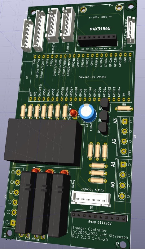
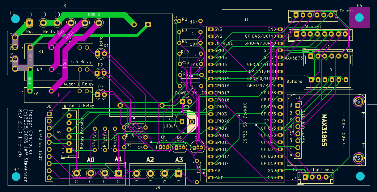
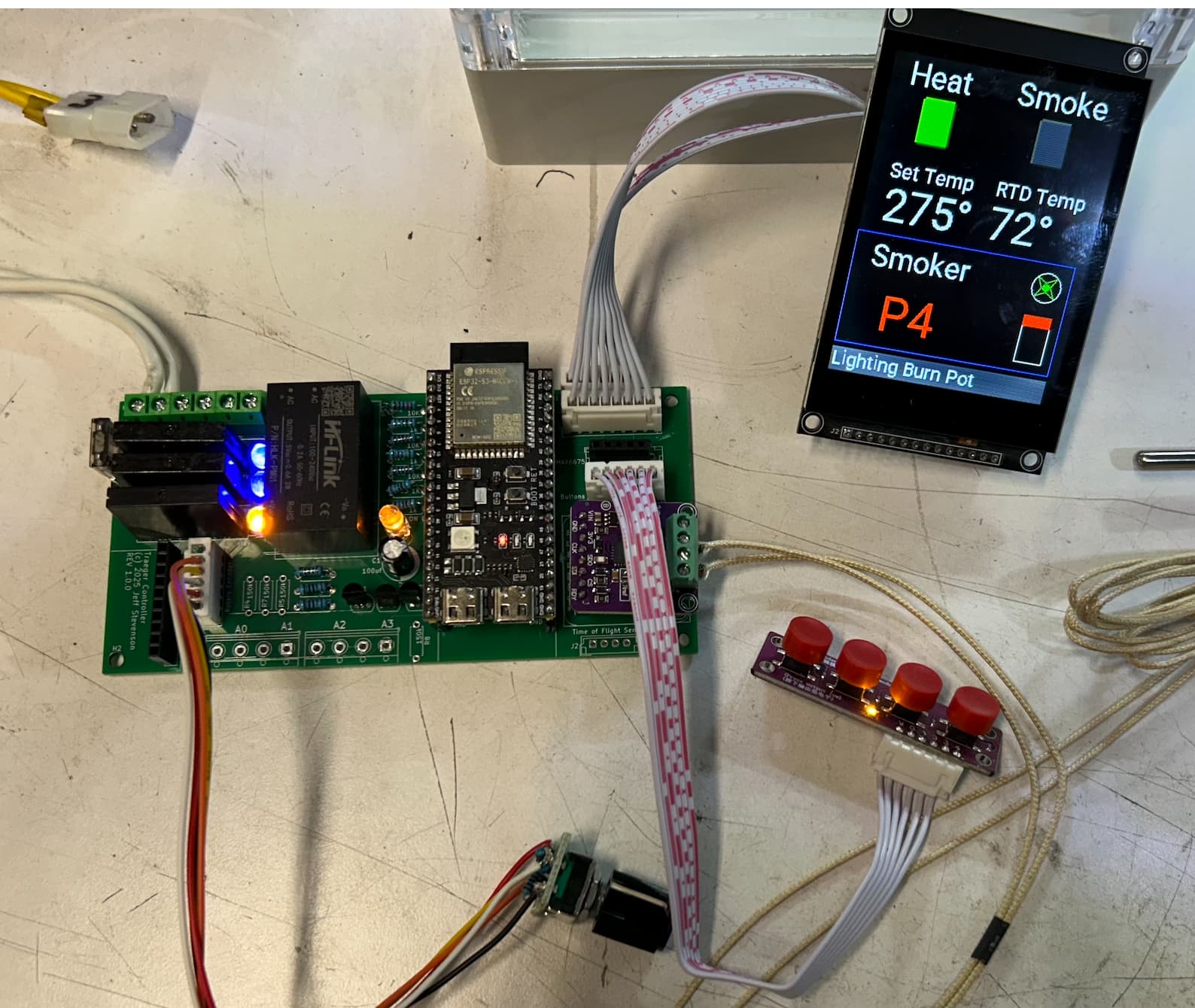
Generic "Traeger" Smoker/Grill controller

I am very interested in this project. I tried uploading your file to jlcpcb but does not seen to know the dimensions of the board from the file. Are you selling these boards? Do you have a component BOM?

Not sure what I am doing wrong on trying to up load your file but if you can give any info I would appreciate it.

Thanks.

Hmm. That’s odd.

I have several boards - happy to send you one. I’ll have to look closely at the board when I get home - I may have made one change to fix a mistake. I just can’t recall.

I also have all the main components including the correct ESP, power supply etc and could make you a pkg deal! I buy components in bulk.

Jeff

you bet just let me know how much!

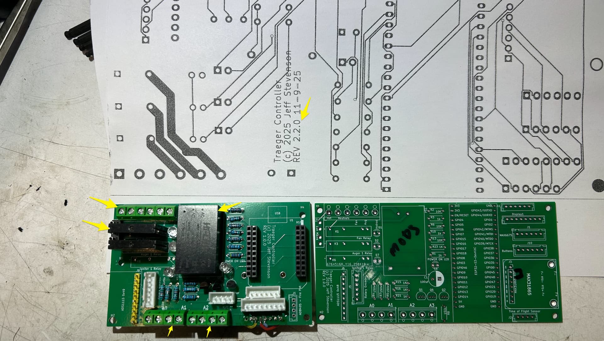
Looking at my boards I did have to make several mods as a result of my rookie KiCad mistakes. I think the best thing is for me to order some new boards incorporating all the fixes I and others have identified. I have several friends that have seen mine and want me to build one.

@blaster452, I have set this aside for you though. It was the first prototype using the D1 Mini (before I went to. the S3), but the PS, relays, headers, etc are all there, you’d just need to unsolder them. I also have the right ESP32 (I have LOTS of them).

So, give me a few weeks to get new boards. I use the slow shipping method to keep the costs down.

I also tweaked the ESP footprint (the pins on the footprint I found were 1mm too close together), and moved it so it’s now fully over the circuit board and rerouted everything.


I think this will make for a cleaner install. Now its off to the fab house!

Jeff

Sounds great keep me updated.

Hi Jeff, this Project looks awesome!
I’m currently planning to set all of this up for my own Traeger. While looking at the Traeger-D1.yaml I noticed that you include a yaml for the touchscreen (common/IPS4.0_touchscreen_(esp32S3_Trager_1pot).yaml). Would you mind uploading this file to your Github project? Would be much appreciated! :smile:

Kind reagrds
Jan

My bad. I just put it there. You can put it in a different file or include it inline w/ the std ESPHome config file. Here are the lines to add

touchscreen:
  - platform: ft63x6
    i2c_id: i2c_bus
    interrupt_pin: GPIO47
    reset_pin: GPIO48
    id: my_touchscreen
    #update_interval: 25ms
    calibration:
      x_min: 0
      x_max: 239
      y_min: 0
      y_max: 319
    transform:
      mirror_x: false #upper left corner is 0,0
      mirror_y: false
      swap_xy: false
    on_touch:
      - lambda: |-
            ESP_LOGI("calibration", "x=%d, y=%d, x_raw=%d, y_raw=%0d",
                touch.x,
                touch.y,
                touch.x_raw,
                touch.y_raw
                );

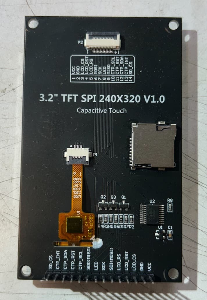
And here’s the best touchscreen I’ve come across so far - you can actually read it in sunlight. Mostly!


https://www.aliexpress.us/item/3256809468856512.html

I’d like to also request a component BOM and updated PCB to your github. I’d love to get a hold of one of these as well. This looks pretty awesome.

The components are all listed on the schematic. If someone wants to create a BOM, I’m happy to post it on my GitHub.

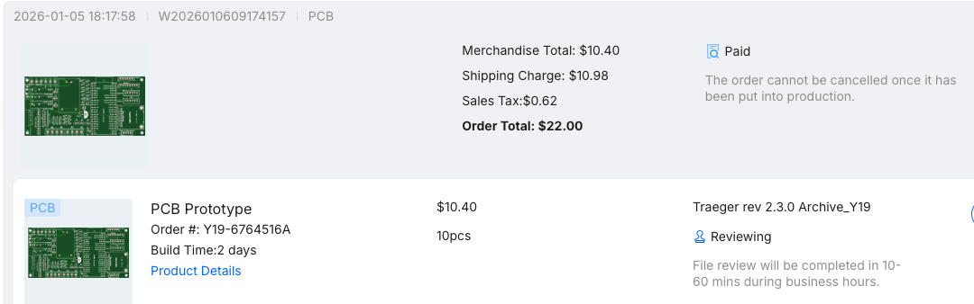
New circuit boards are on the way - I got the speedpak shipping so it will be a couple weeks. Once I’ve tested it, I’ll upload the new KiCad files as well.

Estimated date of arrival at the post office

28 Jan 2026 - 30 Jan 2026, 17 - 19 days remaining

Boards arrived and I’m testing them now. So far so good, I’ve tested the relays work, and will test the other components in a day or so. Once that’s done I’ll have one fully assembled, working board and several other blank boards for those who want them. I don’t have extra displays though.

UPDATE: I can confirm everything works with the new circuit boards

Very nice! Would you mind uploading the updated pcb files on Github? I’m located in Germany and it would probably be easier to get them made locally rather than shipping them all the way here. Also I tried searching for matching relays for the fan, hotrod etc. but didn’t find anything. Did you reuse original Traeger relays or do have you some kind of model number I can search for?
Thanks again for sharing your progress and hard work with us :pray:

Happy to. Will try and do it tomorrow.

The SSR’s are non-zero cross - required for inductive loads which the auger motor and fan are.
Part number is OMRON G3MC-202PL

https://www.mouser.com/ds/2/307/090600_OMRON_G3MCcatasheet_J28I-E-01-493722.pdf

AliExpress is littered with them and you can also find them used on eBay. The PL suffix is the important part that designates non-zero cross. Technically you could use the zero cross version for the hot Rod as it is a resistive load but I just use all the same relays.

Great thanks for the update.I am still interested.

All KiCad files are now in my repository along w/ the gerbers and a Bill of Materials.

ESP32S3-N16R8 I use is this one:
https://www.aliexpress.us/item/3256807334622166.html?spm=a2g0o.order_list.order_list_main.25.24e71802ShBA4D&gatewayAdapt=glo2usa

I haven’t tested or installed the ADC or the TOF modules bc I don’t use them (yet), But they should work fine. Mostly I added those bc I figured other folks might want to play with them.

I now have plenty of boards for sale. Shipping is usually around $5 in the USA w/ my discounts I get for my business.

$15 includes the board & JST headers.
$23 and I’ll include an ESP32C3 - The one I use. I bought a boatload of them.

email me at [email protected] w/ your address & phone number and I’ll give you Venmo/Paypal instructions
Thanks for all your work.

For those of you building this project, and there are now several, I’ve found that if the system is powered off for an extended period of time and you turn it back on, the display comes up blank. HA can control it, but no display. Power it off briefly and back on, and the display comes right back. It’s a power on reset issue somewhere, yet TBD. Unsure if it’s ESP related or display related, but likely the latter. I haven’t taken the time to figure it out… if one of you figures it out, let the rest of us know what the fix is! It could be cad simple as adding an additional RC circuit ( or just an additional 1, 5 or 10uf cap) to the LCD_RST pin on the display to allow a longer time for the display to boot up while the ESP is booting.

I recently received a prebuilt board from Jeff, and wanted to share my experience getting it going and the result (sample size of one cook) on my traeger tailgater.

Getting things connected was fairly straightforward, thanks to the nice silkscreening on Jeff’s board. On my grill, there wasn’t anywhere to mount it, so I elected to use a 3d printed enclosure I had from another project with a couple extra mounts printed for the board and screen.

Initially I was having trouble with the RTD temperature, but that was because I hadn’t soldered the pads on my MAX31865 board to enable two wire mode. I didn’t see that mentioned anywhere and have never used one of these boards but that was an easy enough solve.

I did notice the behavior mentioned in the previous post about the screen coming on but being blank. At first I thought I must have accidentally broken something, or unplugged it while putting it all together but found a quick press of the reset button it would just fire right up again and be working.

The next thing for me was figuring out ESPHome, and getting the device on my home network and piped into my home assistant. I have no previous experience with esphome, but was able to get things going without too much trouble. I used the yaml files supplied in Jeff’s GitHub for the project, and made sure to add in the section for the touchscreen since I am using one.

Once going, I tested it out cooking some chicken thighs and am very pleased with the performance. Without changing any of the configurable parameters, my temps at 225 were very stable. I wanted to finish the cook at 350, but the grill did struggle to get past 330 so it sat there until I was done. I’ve uploaded my temperature graph and settings into ChatGPT, and will try out its suggestions in a day or two. You’ll be able to see in my graph where there are sharp dips, that is when the lid was opened. Recovery was very quick with very little overshoot. A far cry from how things were before with the old dumb controller. Blue line is the RTD temperature, and the yellow is the temperature error.

One final thing was intermittent dropping of my wifi connection, meaning I temporarily lose remote control. I suspect where the grill is located is the problem, and maybe even the screen being overtop is hurting wifi performance.

Anyways, big thanks to Jeff for the project. It’s very cool, and really makes my grill a more hands off unit giving me more time to be doing things other than babysitting it out in Canadian winter.

GitHub link

I could only post one picture per post, since I am a new user, so here’s a picture of my electronics mounted in the box.

Nice! Graph looks good.
Most pellet based cookers take forever to reach temps like 350F. On my 3 burner commercial units it takes 15-20 minutes or more to go from 225 to 350 with the firepods all running full tilt. My partner is building a 5 burner enclosure and I’ve built the controller for it right now. I’m guessing that thing will get to 450 to do reverse Sears in no time…

Wifi dropouts - yup. A big deal. Short of adding more AP’s (they multiply like rabbits in my house) I successfully added external antennas to my critical devices like my pellet stoves and my Traeger controllers. Signal strength went from like -80db with just the ESP32 built in ant to - 30db with the external ant. Problem permanently solved!

I think I did a post on how to do this - I’ll have a look and post the link.

Yup, found it. HIGHLY worthwhile!

Yeah it wasn’t overly fast, but I did appreciate how controlled it was on the way up. I like the gentle curve. That was one of the things I told ChatGPT about and it had a couple ideas on settings that might help so we’ll see.

Thanks for the link, I’ll look into that next