Custom firmware ESPHome-Xiaomi_bslamp2

I’m editing this first post to make it easier for everyone without reading a very long and possible complicated thread.
This has been a long journey to enable LAN control on a Yeelight bslamp2 after a FW-update that revoked the LAN-control functionality from everyone that blindly upgraded to 2.0.6_0041 and beyond.

@mmakaay has done some serious reverse engineering of the bslamp2 and made an alternative firmware based on ESPHome which available at GitHub for us all. Please be sure to thank him, and do buy him a :coffee: or any other beverage he prefers! :wink:

Repository:

13 Likes

The ESP32 chip is a ESP32-WROOM-32D

Sounds like 2 companies whose products I should avoid purchasing

2 Likes

Some random pictures form inspecting the .bin file with strings command in Linux. Looks like some sort of Phyton, but here I’m out of my depth, guys…

My thoughts exactly. But again… they have some nice products at good prices if we can do something about their FW. Being proprietary and forcing HA people into a corner is never a good idea :wink:

Think you can get ESPHome on it?
The PCB looks like a fairly well thought out design at first glance

I really like the bedside lamp and it normally sits in the kids room. Definitely possible considering the ESP32 chip, but then we would need some expertise on the field of ESPhome.
It also looks like it would be possible to do something with BT. A whole lot of programming for it in the FW but it’s not activated…

Possibly good news, guys! Someone has referred to this topic on the Yeelight forum where Yeelight and Xiaomi has received a lot of heat for shutting down the LAN control, and Yeelight have finally decided to release a version that allows LAN control for those who need it. The caveat is that you can’t ever have another FW upgrade and I don’t know if they are locking down the ESP32 in this version. These chips are fairly cheap though so as long as you know your way around a soldering iron you could just swap it for a new one.

I also opened a topic over at “ESPHome” on this forum and tom_l had som good insight to install ESPHome on the bslamp2! I’m quite new to this so I will have to read up and test the “light” module, but I think that I am heading this way for now since there are considerable upsides doing it this way.
If anyone knows their way around ESPHome and want to contribute/educate the rest of us it would be very much appreciated!

1 Like

Hello,

I have one bslamp2. The latest firmware version i can see is the 2.0.6._0030.
In which server do you have the app? china?

Did you try the homekit connection with HA? I think it works over lan, so you could retrict internet connection in your router to the bslamp2.

I’m slightly unsure when it comes to the differences in FW versions in different regions, but you should thread carefully before updating since there is no changelog to review beforehand.
The HomeKit bridge doesn’t give you the ability to do much with the bslamp2 other than turning it on/off as I recall from my testing.

Okay, being annoyed with losing support for my beside lamps, I too started butchering my beside lamp to see where it would get me with ESPHome.

I also traced the serial port pins, GPIO0 and GPIO2 (looking at the pinout image that was posted earlier, GPIO2 is the debug pad to the left of the QR code sticker).
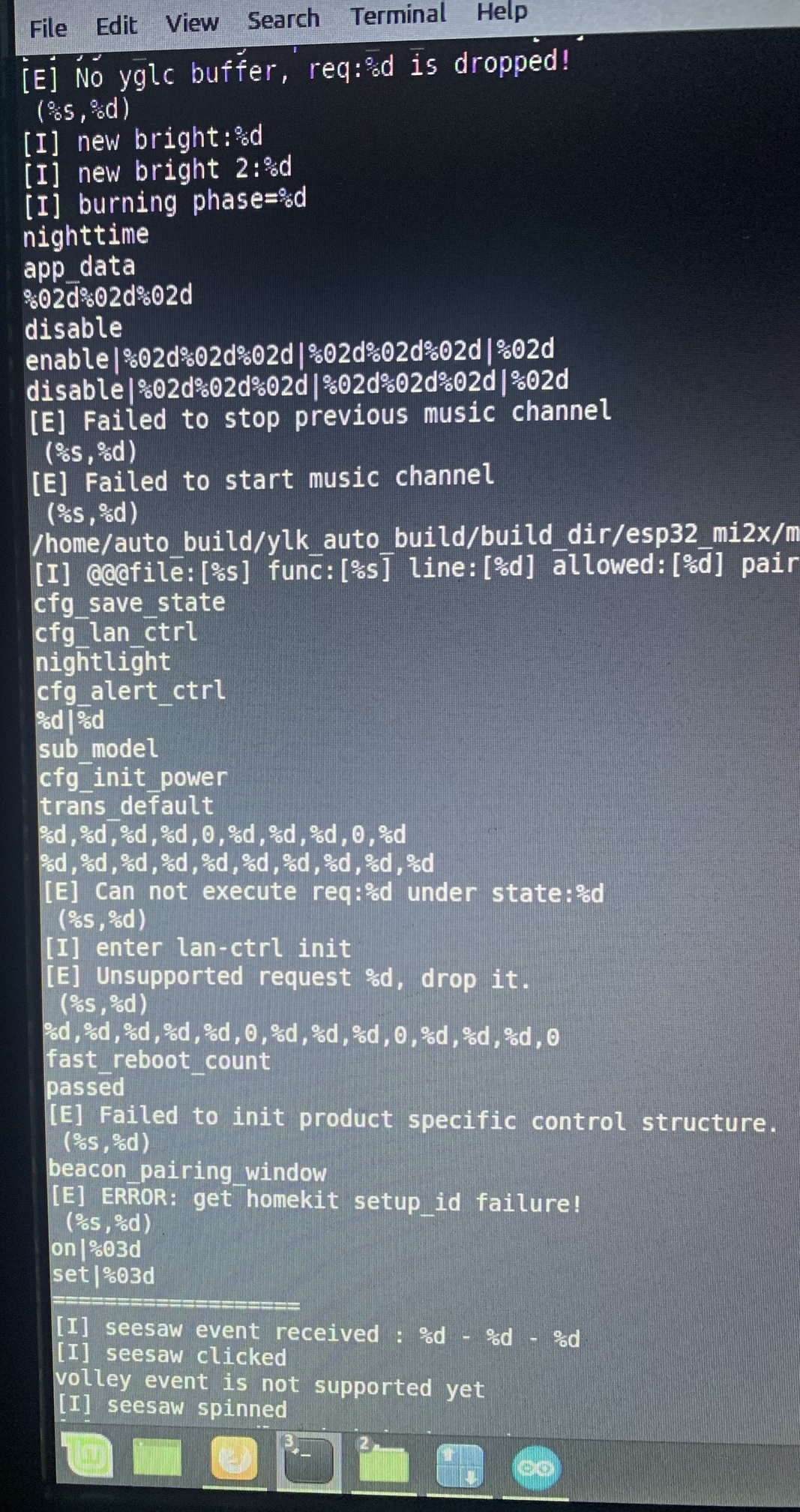
After connecting these to an FTDI adapter, I was able to see logging output from the board. So far so good.

Next step I took, was trying to compile an ESPHome firmware and flash it to the device. To get the device into flashing mode is a bit fiddly, but can be done. The steps that I took were:

  • Get the ESPHome flashing tool ready with the correct COM port and firmware selected
  • Unplug the FTDI adapter
  • Connect GPIO0 to ground (I used the large ground-connected area that is near the LED leads)
  • Plug in the FTDI adapter and start flashing from the ESPHome flashing tool
  • Once the log shows that flashing has started, you can disconnect GPIO0 from ground

This worked, but not very well. The boot process was stuck in a loop, showing an error about the firmware being built for dual core, while the device is single core:

[02:20:09]rst:0xc (SW_CPU_RESET),boot:0x12 (SPI_FAST_FLASH_BOOT)
[02:20:09]configsip: 0, SPIWP:0xee
[02:20:09]clk_drv:0x00,q_drv:0x00,d_drv:0x00,cs0_drv:0x00,hd_drv:0x00,wp_drv:0x00
[02:20:09]mode:DIO, clock div:2
[02:20:09]load:0x3fff0018,len:4
[02:20:09]load:0x3fff001c,len:1044
[02:20:09]load:0x40078000,len:8896
[02:20:09]load:0x40080400,len:5828
[02:20:09]entry 0x400806ac
[02:20:09]E (352) cpu_start: Running on single core chip, but application is built with dual core support.
[02:20:09]E (353) cpu_start: Please enable CONFIG_FREERTOS_UNICORE option in menuconfig.
[02:20:09]abort() was called at PC 0x40082169 on core 0
[02:20:09]
[02:20:09]Backtrace: 0x4008c66c:0x3ffe3be0 0x4008c89d:0x3ffe3c00 0x40082169:0x3ffe3c20 0x40079053:0x3ffe3c40 0x400790b9:0x3ffe3c70 0x400790c4:0x3ffe3ca0 0x4007928d:0x3ffe3cc0 0x400806de:0x3ffe3df0 0x40007c31:0x3ffe3eb0 0x4000073d:0x3ffe3f20
[02:20:09]
[02:20:09]Rebooting...

To fix this, I had to modify my build configuration file. This is what I ended up with (thanks to some other people that figured this out for another kind of device):

esphome:
  name: bedside_lamp_office
  platform: ESP32
  board: esp32doit-devkit-v1
  platformio_options:
    platform: [email protected]
    platform_packages: |-4
          framework-arduinoespressif32 @ https://github.com/pauln/arduino-esp32.git#solo-no-mac-crc/1.0.4

After building and uploading this firmware, I got stuck in yet another reboot loop, but this one looked kind of promising. I saw brownout errors, and I figured that these might be caused by the rest of the circuitry drawing current away from the ESP32, since it was only powered by the 3.3V lead on my FTDI adapter.

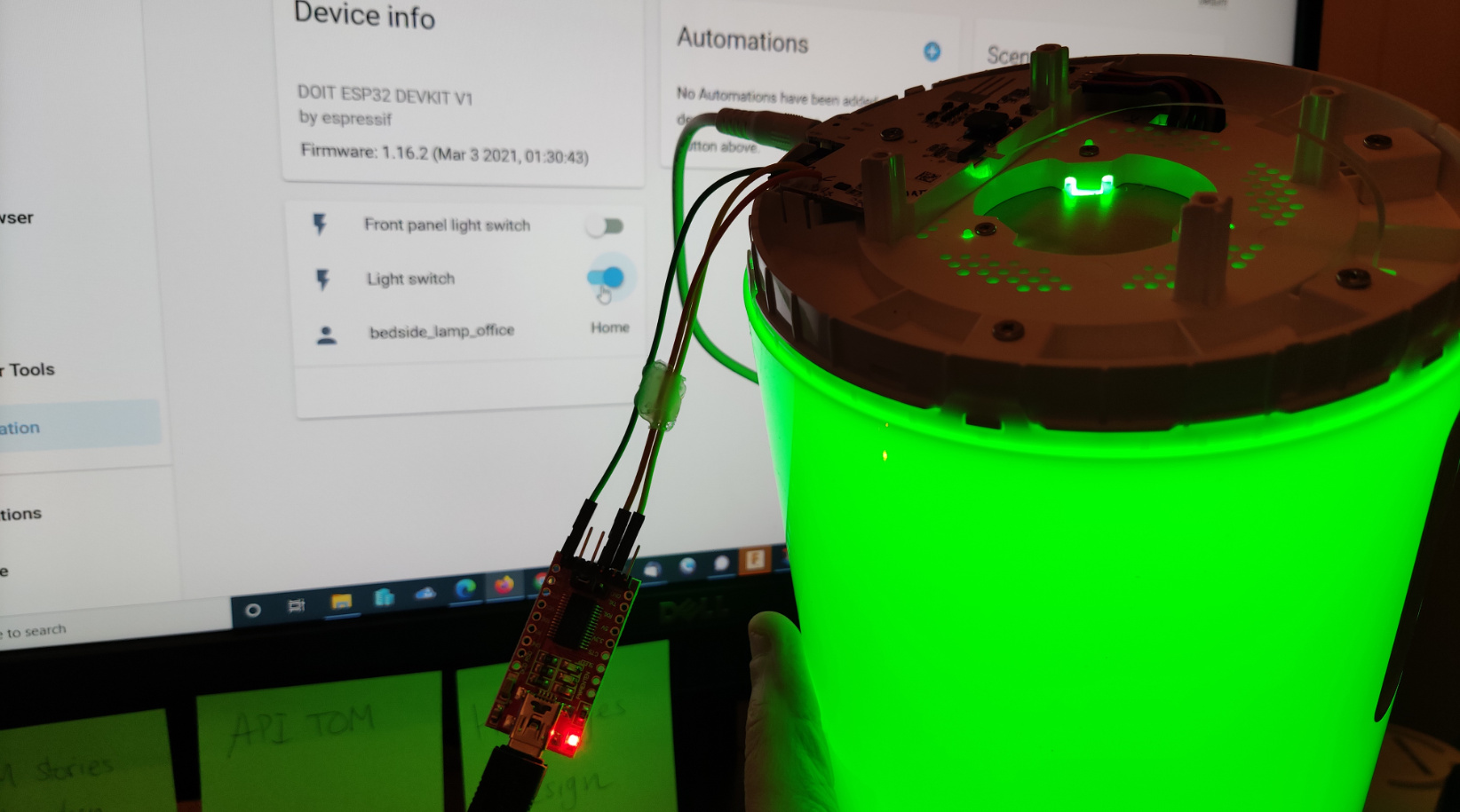
So next step was to disconnect that 3.3V lead and instead powering the device using the regular power supply. I kept the RX/TX pins connected to be able to see the device logging, and that was satisfying to see!

Using 'COM3' as serial port.
Showing logs:
[02:33:17]
[02:33:18][02:33:18]
[02:33:18]rst:0x1 (POWERON_RESET),boot:0x12 (SPI_FAST_FLASH_BOOT)
[02:33:18]configsip: 0, SPIWP:0xee
[02:33:18]clk_drv:0x00,q_drv:0x00,d_drv:0x00,cs0_drv:0x00,hd_drv:0x00,wp_drv:0x00
[02:33:18]mode:DIO, clock div:2
[02:33:18]load:0x3fff0018,len:4
[02:33:18]load:0x3fff001c,len:1044
[02:33:18]load:0x40078000,len:8896
[02:33:18]load:0x40080400,len:5828
[02:33:18]entry 0x400806ac
[02:33:18][I][logger:166]: Log initialized
[02:33:18][C][ota:366]: There have been 1 suspected unsuccessful boot attempts.
[02:33:18][I][app:029]: Running through setup()...
[02:33:18][C][wifi:033]: Setting up WiFi...
[02:33:18][D][wifi:324]: Starting scan...
[02:33:21][D][wifi:339]: Found networks:
<long list of wifi networks in my neighbourhood>
[02:33:21][I][wifi:194]: WiFi Connecting to 'MY CONFIGURED AP'...
[02:33:22][I][wifi:457]: WiFi Connected!
[02:33:22][C][wifi:303]:   SSID: 'MY CONFIGURED AP'
[02:33:22][C][wifi:304]:   IP Address: 192.168.100.159
[02:33:22][C][wifi:306]:   BSSID: AA:AA:AA:AA:AA:AA
[02:33:22][C][wifi:307]:   Hostname: 'bedside_lamp_office'
[02:33:22][C][wifi:311]:   Signal strength: -40 dB ▂▄▆█
[02:33:22][C][wifi:315]:   Channel: 11
[02:33:22][C][wifi:316]:   Subnet: 255.255.255.0
[02:33:22][C][wifi:317]:   Gateway: 192.168.100.1
[02:33:22][C][wifi:318]:   DNS1: 192.168.100.1
[02:33:22][C][wifi:319]:   DNS2: 0.0.0.0
[02:33:22][D][wifi:466]: Disabling AP...
[02:33:22][C][ota:029]: Over-The-Air Updates:
[02:33:22][C][ota:030]:   Address: bedside_lamp_office.local:3232
[02:33:22][C][ota:032]:   Using Password.
[02:33:22][C][api:022]: Setting up Home Assistant API server...
[02:33:22][I][app:059]: setup() finished successfully!
[02:33:22][I][app:105]: ESPHome version 1.16.2 compiled on Mar  2 2021, 01:25:09
[02:33:22][C][wifi:443]: WiFi:
[02:33:22][C][wifi:303]:   SSID: 'MY CONFIGURED AP'
[02:33:22][C][wifi:304]:   IP Address: 192.168.100.159
[02:33:22][C][wifi:306]:   BSSID: AA:AA:AA:AA:AA:AA
[02:33:22][C][wifi:307]:   Hostname: 'bedside_lamp_office'
[02:33:22][C][wifi:311]:   Signal strength: -36 dB ▂▄▆█
[02:33:22][C][wifi:315]:   Channel: 11
[02:33:22][C][wifi:316]:   Subnet: 255.255.255.0
[02:33:22][C][wifi:317]:   Gateway: 192.168.100.1
[02:33:22][C][wifi:318]:   DNS1: 192.168.100.1
[02:33:22][C][wifi:319]:   DNS2: 0.0.0.0
[02:33:22][C][logger:185]: Logger:
[02:33:22][C][logger:186]:   Level: DEBUG
[02:33:22][C][logger:187]:   Log Baud Rate: 115200
[02:33:22][C][logger:188]:   Hardware UART: UART0
[02:33:22][C][captive_portal:169]: Captive Portal:
[02:33:22][C][ota:029]: Over-The-Air Updates:
[02:33:22][C][ota:030]:   Address: bedside_lamp_office.local:3232
[02:33:22][C][ota:032]:   Using Password.
[02:33:22][C][api:095]: API Server:
[02:33:22][C][api:096]:   Address: bedside_lamp_office.local:6053

Home Assistant was happy too, since it notified me that a new ESPHome device was discovered.
I was indeed able to see the device on my network. So next test: can I use OTA updating? Well, look for yourself:

INFO Successfully compiled program.
INFO Resolving IP address of bedside_lamp_office.local
INFO  -> 192.168.100.159
INFO Uploading /config/bedside_lamp_office/.pioenvs/bedside_lamp_office/firmware.bin (861792 bytes)
Uploading: [============================================================] 100% Done...

So the basics are done, I am now the proud owner of a non-functional bedside lamp :wink:
Next steps would be:

  • to find oud what pins to use for the various LEDs. It looks like an RGBW OR RGBWW style setup, because of the names on the leads (which say: R-, R+, G+, B+, W-, W+).
  • to find out how the power button and slider work. There are five leads, GND + 4 others, going to the break out board that hold these, and my bestguess is that the slider might be linked to an analog input and the button to a digital one. However, since there is quite a bit of hardware on the break out board, amongst which an IC with 32 pins that I don’t recognize (but I’m not that well-versed in IC-ology), the communication to the main boar could be really anything.

Tomorrow I will investigate a bit further and see if I can come up with at least some controllable LED lights. Would be nice to get this working.

4 Likes

Okay, I’m a few steps further. After doing a lot of circuit tracing, measuring voltages and figuring out what goes where, I think I have a pretty good set of GPIO’s that I can use to build something in ESPHome. Measuring looked really cool once it got dark btw :slight_smile:

What I got working a minute ago is a switch in Home-Assistant, which turns on the light using a green color. Not yet a full fledged integration, but making good progress here.

Unfortunately, things don’t seem to be as simple as assigning a few RGBWW GPIO’s to the built-in ESPHome RGBWW Light module. The circuitry uses custom circuitry to drive the LEDs and things don’t look standard to me. Based on my measurements, I am now trying to back engineer how to drive the GPIO’s for getting good results.

BTW, for those interested, here are my voltage measurements, taking during various lighting modes:

Some first observations:

  • GPIO 4 and 33 are always on when the light is on, and off when the light is off.
  • Experimentation result: to turn on the light, only GPIO 33 is required, GPIO 4 is likely related to the front panel on the device.
  • In RGB mode, GPIO’s 14 (green), 13 (red) and 5 (blue) are used.
  • High voltage on a GPIO dims the light, low voltage makes the light bright.
  • In white light mode, GPIO 12 is used in addition to the RGB mode GPIO’s. So there are not two separate GPIO’s that are usd for warm and cold white light (which is what RGBWW would expect, so therefore I rules that one out).
  • Experimentation result: you don’t want to look to the LEDs when they are at full brightness, without the housing on :wink:
  • Measurements that are grayed out were done on GPIO’s that I selected as “very likely to be in use on the device”, but which apparentely had no relation to driving the lights. These GPIO’s are good candidates for investigating how the front panel works.

Next goal: create an RGB light, working from Home Assistant. I’ll ignore the white light options for now to keep things manageable.

1 Like

Cheers, Maurice! And welcome to the frustrated few that wants to make this work :grin: I don’t have my lamp at hand for the time being so I haven’t had the opportunity to do much digging, but I see that you have put some work into this. Nice :+1:t2:

When I had a look at the original FW I do remember that GPIO 4 was linked to a “Xiaomi test mode”? No idea what this do, though.
I also saw a lot of strings for I2C. Could it be that this is used to communicate with the LED driver chip?

Looking at this I’m more leaning to your theory on the GPIO 4 and 33 usage:

Capacitive touch GPIOs

The ESP32 has 10 internal capacitive touch sensors. These can sense variations in anything that holds an electrical charge, like the human skin. So they can detect variations induced when touching the GPIOs with a finger. These pins can be easily integrated into capacitive pads, and replace mechanical buttons. The capacitive touch pins can also be used to [wake up the ESP32 from deep sleep]
Those internal touch sensors are connected to these GPIOs:

  • T0 (GPIO 4)
  • T1 (GPIO 0)
  • T2 (GPIO 2)
  • T3 (GPIO 15)
  • T4 (GPIO 13)
  • T5 (GPIO 12)
  • T6 (GPIO 14)
  • T7 (GPIO 27)
  • T8 (GPIO 33)
  • T9 (GPIO 32)

I’m now up to the point that I implemented a custom RGBWW light component for ESPHome, and using that one I am able to control the lamp at the RGB level. This looks promising.

One thing that I already love, is that I can bring down the brightness of the lamp a lot further than the original firmware allows for! The original has the night light feature, but I always missed brightness levels between the night light and the least bright normal light level. This also allows me to setup a night light in a specific color, where the original firmware has a locked in color setting for it. So the future is bright… and dim :smiley:

Next stop: implementing the cool/warm white light, but for that one I want to do more measurements on my other lamp that is still on the original firmware, to figure out the way in which the white light settings translate to GPIO output levels.

2 Likes

I thought about the capacitive touch sensors, since that is what the front panel is using. However, because of the not-so-little IC on that panel and the fact that there are only 5 leads going to the main board (which include Vin and GND for the panel break out board), I don’t think that capacitive touch sensoring is in use here on the ESP32 itself. It’s likely that the front panel does all the heavy lifting, providing a simple interface to the ESP32 (I sincerely hope :laughing:)

My working theory on this, is that the 5 leads are used for something like:

  • Vcc 3.3V
  • GND
  • touch button (this one could be capacitive, but I find it likely that this is translated to binary on/off in the breakout board, before sending it to the ESP32)
  • slider touch value (could for example be an analogue representation of the touched value on the slider)
  • slider level feedback, used to set the slider light indicator to the correct height

But I did not yet do any measurements or full tracing of this part of the lamp, so this is a best guess only.

I also saw a lot of strings for I2C. Could it be that this is used to communicate with the LED driver chip?

Driving the LED circuitry seems to be fully based on PWM outputs directly, no I2C communication there. It could however be the way that the ESP32 is communicating to the front panel. Hadn’t thought about that as an option (still hoping for a simpler interface there :slight_smile: ), but I will look into that. Thanks for the pointer.

The chip on the front panel (ChipON KF8TS2716), is probably this one. When ditching its data sheet in Google Translate, I find that this is a chip that provider quite a few capacitive touch sensors, alongside communication features like SPI and I2C.

Since we have five leads, I think that we can conclude that this is not SPI, since that uses 4 logic pins. Two of our leads are for Vcc/GND, leaving us with only 3 leads, which is not enough for SPI. I might be wrong here, because I’m speaking as a true amateur here :wink:

I’ll see if I can enable I2C in the ESPHome firmware. That module also does an optional scan of the bus on startup IIRC, so if the front panel does talk I2C, it should be visible in the scan.