The mbus master module just came in.
It turns out that the slave module does not communicate on its own - it sends frames only when polled by a master.
So currently I am searching for any option to integrate mbus master module with home assistant, ideally with ESP 
1 Like
Presuming that you need a master to poll the slave meters, did you find one that worked, and just to check, I’d then need something to decode the output from the master to get it into ESPHome and then into HomeAssistant?
Sorry just starting out on this HA journey. I just bought some M-Bus meters on an auction site and want to read them remotely so I can track consumption.
How can you read a meter with a slave module?
Hi @Oleksii_Zelivianskyi
I want to read my Kamstrup multical 21water meter mbus.
did you fint any usefull solutions ?
Hi all,
This topic is quite old, but it shows up at the top, when asking google about ESPhome and mbus. First, I want to state, that M-Bus and wireless M-Bus are quite different. They look quite similar when it comes to interpretation of the data, but widely used wmBus slaves transfer with T1 and send on their own in regular intervals. (wired) M-Bus slaves need to be polled.
Now to the ESPhome questions:
With wireless M-Bus, I see no easy solution to connect it with some ESP or ESP32. You need another radio module (868 MHz) to receive the data. For USB, there are some more or less cheap USB-to-wmBus-Converters (some use DVB-T-Sticks for it, other like me take the IMST iM871A-USB).
With M-Bus, you need a special circuit to level-shift the master’s TX data and also a part of the circuit to measure the current drawn by the slaves (master’s RX). There exist quite many cuircuits from chinese shops (aliexpress) that sell ready-to-use USB-to-M-Bus-Converters. Nevertheless, I also would find it great, if somebody could address it on some ESP32, maybe I’ll do this sooner or later…
With some Raspberry Pi and the mentioned converters, it is much easier to integrate M-Bus and wmBus meters into Home Assistant or other Smart Home systems.
For further Information, I wrote some stuff on my blog about M-Bus and wmBus, so anybody still interested could read through and if still some stuff is not clear, I would be happy to extend my post or answer questions here:
4 Likes
Hi all,
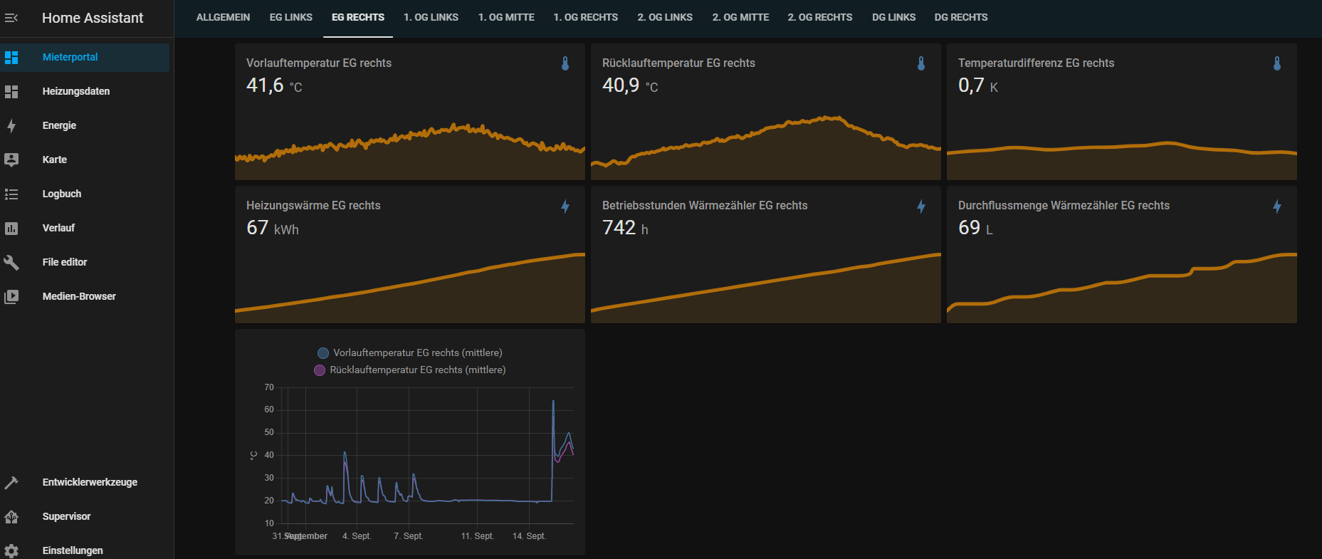
I had the job to integrate 10 heat meters (Zenner Zelsius C5) into HA. They work over M-Bus (Meter Bus) wireless oder wired. I decided to use wires, since we could reuse some existing wires. They act as M-Bus slaves. All slaves are connected to the M-Bus in a star - topology.
The bus is connected to the Gateway. I use one from ADFweb. I decided to use the M-Bus/MQTT Gateway, because this was for me the easiest possibility to get the sensor values into HA.
I had to view, select and configure the M-Bus Parameters and publish them as MQTT-Topics. The Gateway reads the configured M-Bus data, converts it into MQTT-Topics and publishes it to the MQTT server (Mosquitto) in Home Assistant. From there I can easily configure them as sensors.
It is not the direct way, since I have to configure the sensors twice; but after a long research I found this the best solution for my situation.
As a result I get a nice view for every apparment. Something like this:
5 Likes
@klacol thank you very much for sharing. I am looking for a solution to read my water meters as well.
I have a few questions, maybe you know the answers to?
- I see in the ADFWEB specification that the gateway also has the wi-fi config option:
http://www.adfweb.com/download/filefold/MN67931_ENG.pdf
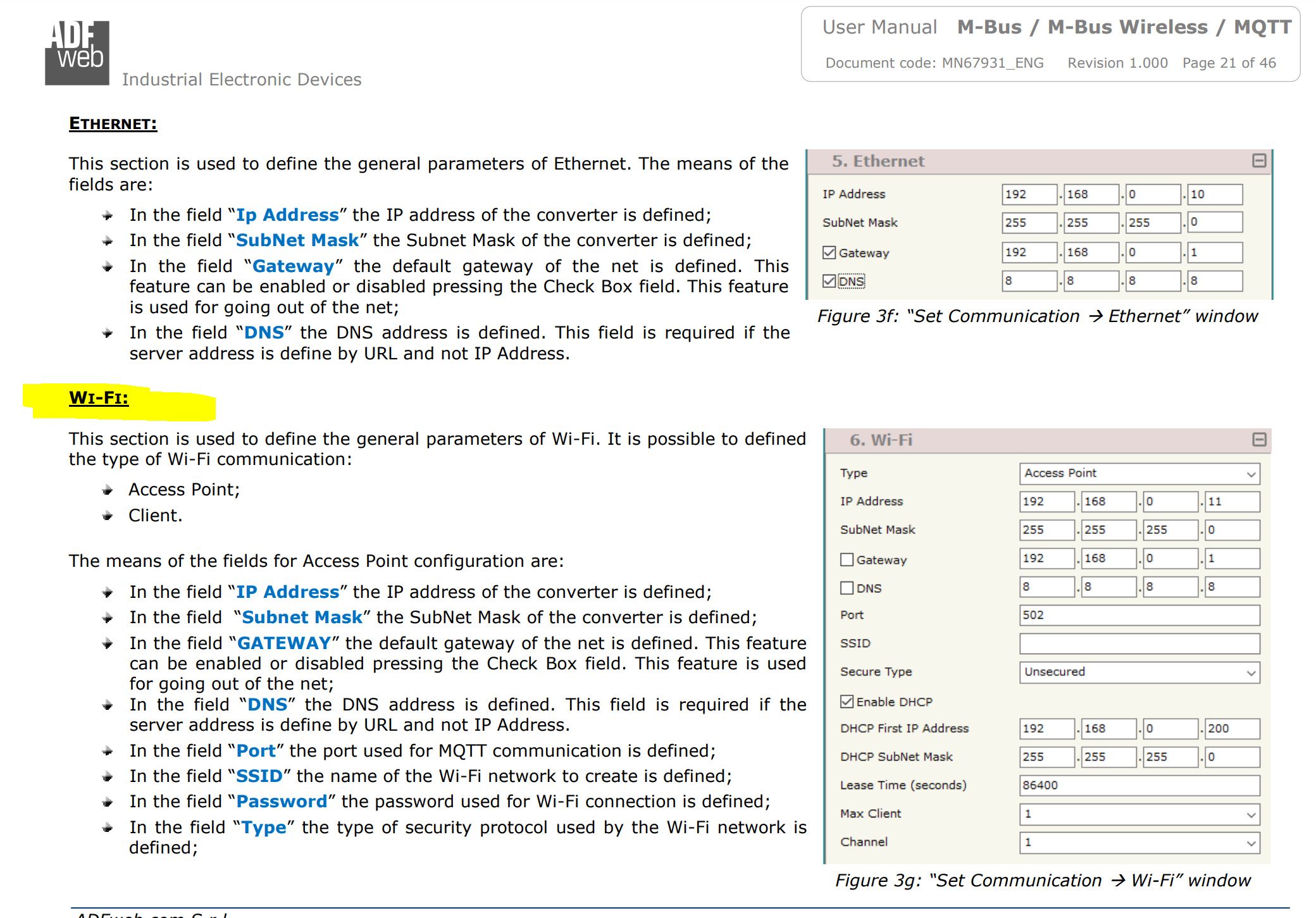
How are you connecting the gateway to your LAN? via the ethernet cable or wifi? I would like to use the wifi and it is interesting if the connection is stable, etc.
- Do you happen to know if several M-BUS masters/gateways can talk to the same meter/device/slave at the same time? I might have a situation where my water company is querying the devices and I would like to install a personal gateway for my HA as well (my understanding is that there should be no problems?)
Thank you.
There is a link further up to the module I am using, with the caveat that I am connecting to a Kamstrup electricity meter that powers the line. Other MBUS devices may behave differently…
@dknt - could you please update how it went for you? Maybe post a link to what mbus master module you ordered? Is everything working for you now? On Rpi, or maybe on ESP? Thank you!
I checked the price. These ADFweb modules are quite expensive for “home use”… 
Modbus_controller has been merged into esphomes dev branch yesterday.
It let’s you connect most modbus RTU devices if you know the modbus registers used by the device.
Documentation is not yet online on esphome.io (but already in the ‘next’ branch.
Until then have a look at
And the staged docs at Modbus Controller — ESPHome

Didn’t know that m-bus is not modbus. Just saw register and got triggered 
3 Likes
I am using it via LAN; I cannot say something about the stability of wifi.
As of my understanding, this should not be a problem. You would have two masters (e.g. the Gateway; sorry they have no other word for this over at MBus) and one Slave (the meter; again MBus-Words). The Gateway queries the meters every x seconds.
It would be good, to have this for M-Bus (Meter Bus) too. The both standards (Modbus and M-Bus) are mixed up very often; so I tend to use the term “Meter Bus” for M-Bus.
I have integrated a gas meter to the M-Bus (Meter Bus) with an pulse reader and a pulse counter . Perhaps, this works for water meter as well. The equipment is quite expensive IMHO, but since I am not the electronic engineer, this was my way. It would be much better, when my gas provider would install a meter, that has a digital interface, but in 2021 they still install gas meters as in 1970 :-(.
I’ve linked a quite cheap (35 bucks) M-Bus solution using a cheap USB-M-Bus-Dongle in my blog I already mentioned before. There you only need to add a small bash script to cron that publishes the sensors found in a first run to MQTT and all you need to do is configuring it once in Home Assistant.
Here is the link to the blog post again (for the lazy ones):
If there is heavy interest in some ESP32 M-Bus master (e.g. to use it with ESPhome), I would put it on top of my list of projects to realize in the near future… But the quick and reliable solution is to use the USB-M-Bus-Master from aliexpress…
@the78mole thank you for sharing your solution.
/1./
My preference would really be to have an ESP32/ESPHome solution for reading M-bus meters.
Firstly, because the meters are physically located quite far away from my RPi, and I would not have to pull two m-bus wires all over my apartment.
Secondly - I have an HAOS installation on an RPi (Installation - Home Assistant) which is a managed OS, and I am not sure how to install third party software like libmbus on it.
So ESPHome would (hopefully) solve those two issues for me.
On that note, I have found another project (to the above Snedig’s), which has implemented it:
Have you checked it?
I am just not sure what are its limitations, would it work on other meters than listed, and would it work with an M-Bus Master module, instead of a Slave.
/2./
Since I am looking forward to connecting it to the ESP32, I have ordered an M-bus Master module with TTL serial port from Ali (17EUR): https://www.aliexpress.com/item/33009939864.html?spm=a2g0s.9042311.0.0.27424c4dlVSRON
In real life it looks like this:


However, I haven’t figured out yet if/how it supplies 30V power to the bus. I have hooked up 12VDC to VIN and GND, but I see 0 DC voltage on the MBUS terminals.
The poorly translated specs on Ali don’t say much:
" 7, M: MBUS bus interface, the initial high level bus 30 ± 1V(customizable)"
Messaging with the seller is fruitless because of the language barrier (or the lack of subject knowledge?).
On the other hand I see in the description of your device it states clearly:
- The module takes power from the USB port of the computer and boosts the internal voltage to 36V.
Maybe you happened to measure the voltage across the MBUS terminals of your module? Does it show ~30V right after you hook it up to the USB port? Or maybe it starts feeding 30V only after some event?
1 Like
Hi paulius,
first of all: Great finding!!! 
No, I didn’t stuble over this solution, even if I searched quite a bit for it…
And yes, I’ve measured the voltage on the M-Bus of my adapter (and did it right now again to make myself certain): It is exactly 30.0…30.1V
This part heavily looks like some simple Step-Up-Converter, but unfortunately, I can not read the exact IC part number. But the coil and the pin-count of the IC lead to this conclusion.

The larger 3-pin part on the left (with AGO naming) seems to be the Step-Up switch, which shortens the output coil pin to ground to store energy on the coil and then release it, to store the higher voltage on the Capacitor (10/50V VT). The diode SS16 is the output diode of the step-up (quite a chaotic design  )
)
The two resistors 203 (20K) and 303 (30K) could be selectable feedpack divider parts for changing the output voltage of the step-up converter to the two levels for TX = HIGH/LOW.
So, you should be able to apply e.g. 12V to Vin and you could measure the M-Bus-Voltage at the right pin of the large capacitor (should be 30V). If this is not the case, the step-up converter is not starting. You should find a datasheet for the IC and look out for enable signal, measure it and find the root cause, if it is deactivated.
If I would have a little more time, I could reverse-engineer the design quite easily with your nice foto shots, but unfortunately (as you can see from the time of my post), I’m currently under quite heavy load.
If you can get a more crispy shot of the little IC, I’ll do my best to support further. Some hint: Take the shot with flash and in an angle around 45 degree. The characters will light up when the angle is just right because of very different reflection properties of the ink and the case. Pictures from the top have often very low contrast.
I’ll already ordered one of these TTL-M-Bus master converters, since I’m planning to also get rid of some long M-Bus wires in my house. But it will be delivered around christmas 
Hope you can report some success soon.
If we finish this successfully, I’ll extend my blog post (or write a second onw) for all to copy the solution, maybe with some more advanced own hardware.
Thanks for sharing also your findings. 
Regards,
Daniel
1 Like