Hayward AquaLogic / ProLogic automation

It occurs to me that if one wants control of the heater set point, it could be accomplished by ceding full control of the heater to Home Assistant.

One would start by setting the heater’s internal setpoint to some exceedingly high (or max) value, higher than any temperature you’d ever want the pool to actually achieve. Then in Home Assistant:

  • establish a helper to store your true desired setpoint temperature value (lower than the heater’s internal setpoint from above)
  • create an automation to watch the water temp to turn the heater on when it drops a couple degrees below the helper value, and turns it off again when the water temp reaches the helper value
  • replace the heater on/off button in the dashboard with one that simply toggles the automation on&off (though you might want another dashboard entity to indicate the heater itself is actually on) a generic thermostat

Haven’t tried it myself, but I think it should work.

Easier way, just create a thermostat for your pool: Generic thermostat - Home Assistant

1 Like

HASS code is on Github. You can get all there. For example, here is Aqualogic code: core/homeassistant/components/aqualogic at dev · home-assistant/core · GitHub

The Core.py you mentioned is part of a PIP requirement that you could find in the manifest.json inside Aqualogic core component. And as all PIP requirements you can find it on the website here: aqualogic · PyPI

I noticed you already worked you way around it, but would be good to know for future endeavors

Upon reading rfnovo’s generic thermostat suggestion above, I got excited to try it. I increased the pool’s physical heater setpoint to 35°C, and in initial testing Home Assistant control seems to work perfectly well.

We don’t typically have the heater (and thermostat) on that often. To safeguard against a runaway heater turned on from the pool fob or control panel, I’ve added an automation to ensure the Home Assistant thermostat also gets turned on.

This looks pretty good, in the absence of an actual controller this could definitely work. Does the controller still run the pump after heater shutdown to cool the heat exchanger?

What entity did you use in the thermostat? Was it something you compiled in your custom component? Can you share that component if so?

I can’t say I’ve actually watched for that, but AFAIA the cool down is managed by the pool controller, and turning off the heater from HA should be no different than doing so at the panel.

The heater entity is aqualogic_heater_1, which is defined in the core but not published as an available switch in the HA integration. A comment in the code leads me to suspect swilson thought it needed more work and had it sort of disabled, but enabling it seems to work fine with my Prologic controller. The target climate sensor is of course aqualogic_pool_temperature.

These are additional entities I made available:

  • sensor is_heater_enabled - heater_1 is “off” when the actual heater is merely idle, this sensor is “true” whether the heater is idle or heating, became less needed after I implemented the thermostat
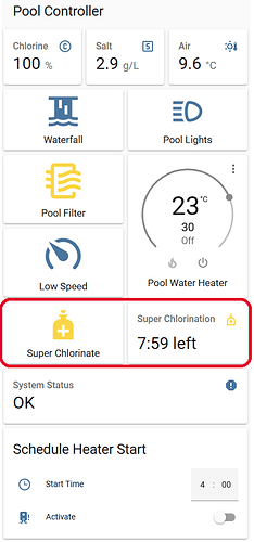
  • sensor is_super_chlorinate_enabled - ‘true’ during super chlorination
  • sensor super_chlorinate_time_remaining - captures the count down timer as text
  • switches aux_8 through aux_14 , my pool only uses 3&4, no idea if >7 work
  • switches valve_3 and valve_4
  • switch heater_auto_mode - this does nothing on my pool
  • switch heater_1

My integration is through a wired serial connection (RS485 USB adapter) and I had to do some mods to make that work, probably wouldn’t affect those using IP but no way for me to test.

I’m happy to share my modifications, but I’m uncertain how best to do that, not sure I want to muddy PyPI. Any suggestions?

Hey! Thanks for keeping this going. I’ve been away from it for a while but thanks to the updated custom component I was able to figure out how to expose my Solar Valve (Valve 3) to HA. I also think that my connection reliability with the remote ESP8266 node improved. A couple of questions:

  • I’m currently using ESP-Link as my Serial-Wifi bridge. Would there be a relatively easy way to use ESPHome instead?

  • Has anyone found a way to access the parameter memory mapping directly, without having to scrape the display printouts? I’d like to access stuff like solar sensor temperature, timer settings, etc. directly, without having to scroll thru display pages. The Century VGreen VS pumps, for example, have this document https://docplayer.net/211417816-Gen3-epc-modbus-communication-protocol.html which lays everything out.

Hey! I just got this working, with a lot of helpful tips from this thread (and of course the great code from swilson). Took me a while to decipher what I needed to do, so I thought I’d post a summary of my experience in case it helps anyone.

My hardware:

  • Hayward ProLogic PL-P-4 control board
  • (Not as relevant, but a Hayward TriStar Variable Speed pump, H-Series Expert Line natural gas heater, and Hayward salt chlorinator)
  • USR-TCP232-304 serial RS485 to Ethernet module, from Amazon.

I had the foresight to drop some cat6 in the trench when they ran the natural gas and electricity to the pool shed, so with some RJ45 crimping, that part was ready to go.

The process:

  • Plug the RS485 module into the network. Use the web UI to configure its IP address etc., and set the serial to 19200 8N2, put it in “TCP Server” mode, and give it a port number to listen on.
  • Unplug the ProLogic and take the front cover off. In the upper left corner of my board, find the green terminal block labeled “Remote Keypad”. Even though I don’t have a remote keypad, there’s wires in here - probably from the local keypad (doesn’t matter, it’s just an RS485 interface).
  • YES there are already wires in it, and YES you’ll be plugging wires from your RS485-to-ethernet into the same terminals. That’s okay. You don’t need a fresh unused block.
  • The RS485 module has three terminals: G, B, and A. Wire “G” to the “GRN” terminal, “B” to the “YEL” terminal, and “A” to the “BLK” terminal. Nothing goes in the red terminal. The RS485 module has its own power supply, so doesn’t need to be wired into power on the board.
  • Follow the instructions on AquaLogic - Home Assistant to enable the integration, and then enable sensors and switches.
  • Contrary to some earlier reports from a couple years ago, I didn’t have any problems with the switches - I can turn the pump and lights on and off from Home Assistant.

Now all that’s left is to set up some automations and dashboards, and maybe poke around in the code to enable some new sensors or switches (if the Prologic is controlling my heater, there should be a switch for it, right? Also my Prologic has a water flow sensor - I’d like to surface that, especially if it has flow rate instead of just Flow/No Flow).

Really sweet job on this.

2 Likes

Just replying to my last point:

… maybe poke around in the code to enable some new sensors or switches (if the Prologic is controlling my heater, there should be a switch for it, right? Also my Prologic has a water flow sensor - I’d like to surface that, especially if it has flow rate instead of just Flow/No Flow).

Looking just above my post at the work of aming-miyembro, it looks like some of this might already be supported in the core python module, and just needs to be exposed in the home-assistant integration. I just got cli.py working, I’ll look around from here.

I just got this working (went without a hitch after reading this thread). I have a PL-P-4 controller and my waterfall is controlled on “valve_3” and I would like to get control of this valve.
Attached is a photo showing where valve3 is. I see additional pinouts for for aux3 to aux 6.

What are my options here?
Also what about turning the heater on and off and setting temperature (think I already know the answer but worth asking anyway)?

Kevin.
I’ve been working on getting valve_3 to work for a while. Mine is my solar diverter valve. I wanted to have my pump speed go to high rpms when the solar valve was on and back to the scheduled rpms when it went off. I got the valve_3 part working. Don’t remember what finally clicked in my brain to figure it out.

Anyway, you’ll have to modify the file “switch.py” in your Aqualogic custom configuration folder to add valve_3 as a “Monitored Condition”. Here is my modified switch.py:

from __future__ import annotations

from .core import States
import voluptuous as vol

from homeassistant.components.switch import PLATFORM_SCHEMA, SwitchEntity
from homeassistant.const import CONF_MONITORED_CONDITIONS
from homeassistant.core import HomeAssistant
import homeassistant.helpers.config_validation as cv
from homeassistant.helpers.entity_platform import AddEntitiesCallback
from homeassistant.helpers.typing import ConfigType, DiscoveryInfoType

from . import DOMAIN, UPDATE_TOPIC

SWITCH_TYPES = {
    "lights": "Lights",
    "filter": "Filter",
    "filter_low_speed": "Filter Low Speed",
    "heater_1": "Heater",
    "aux_1": "Fountain",
    "valve_3": "Solar",
}

PLATFORM_SCHEMA = PLATFORM_SCHEMA.extend(
    {
        vol.Optional(CONF_MONITORED_CONDITIONS, default=list(SWITCH_TYPES)): vol.All(
            cv.ensure_list, [vol.In(SWITCH_TYPES)]
        )
    }
)


async def async_setup_platform(
    hass: HomeAssistant,
    config: ConfigType,
    async_add_entities: AddEntitiesCallback,
    discovery_info: DiscoveryInfoType | None = None,
) -> None:
    """Set up the switch platform."""
    switches = []

    processor = hass.data[DOMAIN]
    for switch_type in config[CONF_MONITORED_CONDITIONS]:
        switches.append(AquaLogicSwitch(processor, switch_type))

    async_add_entities(switches)


class AquaLogicSwitch(SwitchEntity):
    """Switch implementation for the AquaLogic component."""

    _attr_should_poll = False

    def __init__(self, processor, switch_type):
        """Initialize switch."""
        self._processor = processor
        self._state_name = {
            "lights": States.LIGHTS,
            "filter": States.FILTER,
            "filter_low_speed": States.FILTER_LOW_SPEED,
            "heater_1": States.HEATER_1,
            "aux_1": States.AUX_1,
	    "valve_3": States.VALVE_3,

        }[switch_type]
        self._attr_name = f"AquaLogic {SWITCH_TYPES[switch_type]}"

    @property
    def is_on(self):
        """Return true if device is on."""
        if (panel := self._processor.panel) is None:
            return False
        state = panel.get_state(self._state_name)
        return state

    def turn_on(self, **kwargs):
        """Turn the device on."""
        if (panel := self._processor.panel) is None:
            return
        panel.set_state(self._state_name, True)

    def turn_off(self, **kwargs):
        """Turn the device off."""
        if (panel := self._processor.panel) is None:
            return
        panel.set_state(self._state_name, False)

    async def async_added_to_hass(self):
        """Register callbacks."""
        self.async_on_remove(
            self.hass.helpers.dispatcher.async_dispatcher_connect(
                UPDATE_TOPIC, self.async_write_ha_state
            )
        )

The 2 references to valve_3 are added in the blocks "SWITCH_TYPES = { " and “def init(self, processor, switch_type):” (You’d change “Solar” to “Waterfall” in your case)
Then, you add the valve_3 entity to your configuration.yaml file:

switch:
  - platform: aqualogic
    monitored_conditions:
      - lights
      - filter
      - aux_1
      - valve_3

This should work but like I said I don’t remember how I finally figured it out :). Hope this helps.

2 Likes

Ron,
Thanks for this. I have HA running on a Qnap virtual machine (Virtualization Station). I’m a linux noob - how do I get access to these files?

Use the HA File Editor addon so you can do this all in HA. I’m not sure how to access the files for the built-in Aqualogic integration, as opposed to the original Custom Component integration. So I added them from GitHub into an “Aqualogic” folder which is inside a “Custom Components” folder which is in the “/config” folder.

So I can just install swilsons integration, edit with your code and it will override the native integration in HA then? Not clear how I distinguish which one will get used…

I believe so. If you installed swilson’s integration from GitHub, I guess you have a Custom Component. If you haven’t installed it from GitHub you’re using the native integration. Not sure where the native files would be located in your case. Depends on your installation platform, I think. Probably documented somewhere searchable.

Hi @aming-miyembro ,
I’d like to see the work you’ve done to make a USB serial to work. Could you push your changes to a fork on GitHub, and point us to it? If/when you do that, you could also create a pull request to have those changes applied/reviewed for the main source.

My system is a Hayward Pro Logic PL-PS-4. I had to modify some stuff to get cli.py to run, change serial to write() from send(), and deal with display updates where additional byte encodings were used. The system state seems to be read without issue now. When I try to send a serial command like the SPA mode using the cli.py, it doesn’t take effect. Before I start debugging, I’d rather see if/how you’ve dealt with it.

I created a PR on aqualogic source to address the display issues.

Here’s my branch for what it’s worth:

Hey!

Yes, I also applied the send() to write() fix (in core.py) to get my serial connection working properly. Also made the following mod for sending instructions, hopefully it helps you:

        if key.value > 0xffff:
            self._append_data(frame, self.FRAME_TYPE_WIRELESS_KEY_EVENT)
            self._append_data(frame, b'\x01')
            self._append_data(frame, key.value.to_bytes(4, byteorder='little'))
            self._append_data(frame, key.value.to_bytes(4, byteorder='little'))
            self._append_data(frame, b'\x00')
        else:
# MOD BEGIN
            # self._append_data(frame, self.FRAME_TYPE_LOCAL_WIRED_KEY_EVENT)
            self._append_data(frame, self.FRAME_TYPE_REMOTE_WIRED_KEY_EVENT)
            self._append_data(frame, key.value.to_bytes(2, byteorder='little'))
            self._append_data(frame, b'\x00')
            self._append_data(frame, b'\x00')
            self._append_data(frame, key.value.to_bytes(2, byteorder='little'))
            self._append_data(frame, b'\x00')
            self._append_data(frame, b'\x00')
# MOD END

Someone who understands bytecode better than myself might have a better way to write that.

I didn’t use cli.py, no longer remember the issue why. To get output I simply turned logging on (temporarily) in configuration.yaml:

logger:
  default: info
  logs:
    custom_components.aqualogic: debug

I’ve been away from this since the Spring, but hope over the next week to attempt getting a switch working to toggle superchlorination on&off. Once that’s done I might post it all to GitHub – I’ve not used git in enough years that I’d have to relearn it – so no promises at this time.

But feel free to ask any questions!

@aming-miyembro , Thanks! I’ll compare with my latest and see if your changes help.

Button presses go from phases of very reliable to very unreliable. I’ve looked at the various timing suggestions that are mentioned in this thread and the sources they point to. At present, I can navigate the menu system using HA - with patience. The Pool/Filter/etc direct buttons are more reliable probably because the python can retry those since the expected final state is known.

I made an mqtt interface so that I could hack around without the overhead of a custom component.

Done&dusted! It was less difficult than I had expected, made easier by the index of command data in the Hayward AQ-CO-SERIAL manual.

Now that this works, I hope next Spring to add an inexpensive connected ORP sensor to the pool system so Home Assistant can determine when free chlorine is low, so as to automate turning on super chlorination until the chlorine level is satisfactory.


If you have a custom aqualogic implementation for which you do not yet have a superchlorination switch, you can add it as follows:

  1. For switch.py add the following:

    i. to the SWITCH_TYPES array…

    “super_chlorinate”: “Super Chlorinate”,

    ii. to the AquaLogicSwitch class…

    “super_chlorinate”: States.SUPER_CHLORINATE,

  2. For core.py (or keys.py, if there’s no Keys class in core.py) add to the Keys class:

    SUPER_CHLORINATE = 0x04000000

  3. For configuration.yaml, ensure these items are specified:

    sensor:
      - platform: aqualogic
        monitored_conditions:
          - is_super_chlorinate_enabled
    switch:
      - platform: aqualogic
        monitored_conditions:
          - super_chlorinate

1 Like

@b3nj1 @swilson

Hello!
Thank you for all the amazing work you’ve done with Hayward pool hardware interfacing! I was very excited to see this was available for Home Assistant.

I am new to HA since recently switching from Homeseer.

I wonder if you can give me a little insight as to how you created the neat dashboard to navigate the ProLogic menu?

I’ve cloned the pl_ps_4 branch and I am receiving data from my system onto a basic entities card. I’ve added the following to my configuration.yaml file.

#####  Hayward Aqualogic/ProLogic  ##########################################
#####  SENSORS can be found in sensors.yaml  ################################
aqualogic:
  host: 10.0.1.64
  port: 8899

switch:
  - platform: aqualogic
    monitored_conditions:
    - lights
    - filter
    - aux_1
    - aux_2
    - aux_3
    - aux_4

In sensors.yaml:

#####  Hayward Aqualogic/ProLogic Sensors  #################################
- platform: aqualogic
  monitored_conditions:
    - pool_temp
    - air_temp
    - pump_speed
    - status
    - pump_power
    - salt_level

Is it safe to assume that I am using the cloned version as opposed to the native integration?

I also spotted the web.py and web.hml files in the aqualogic folder and they appear to be used for websockets, but I’ve no idea how to create the entities for the LEFT, RIGHT, MENU, + and - which I assume are needed to create a dashboard similar to yours?

Can you provide any suggestions, please?
Thank you again!