It’s similar to op, just 1 live incoming & outgoing

It’s pretty small, fits nicely behind the switch without adding spacer
Oh wait, you’re asking about the no neutral solution, this is my diagram.
It’s similar to op, just 1 live incoming & outgoing
It’s pretty small, fits nicely behind the switch without adding spacer
Oh wait, you’re asking about the no neutral solution, this is my diagram.
yes, same as my stairways , but i thinking about this
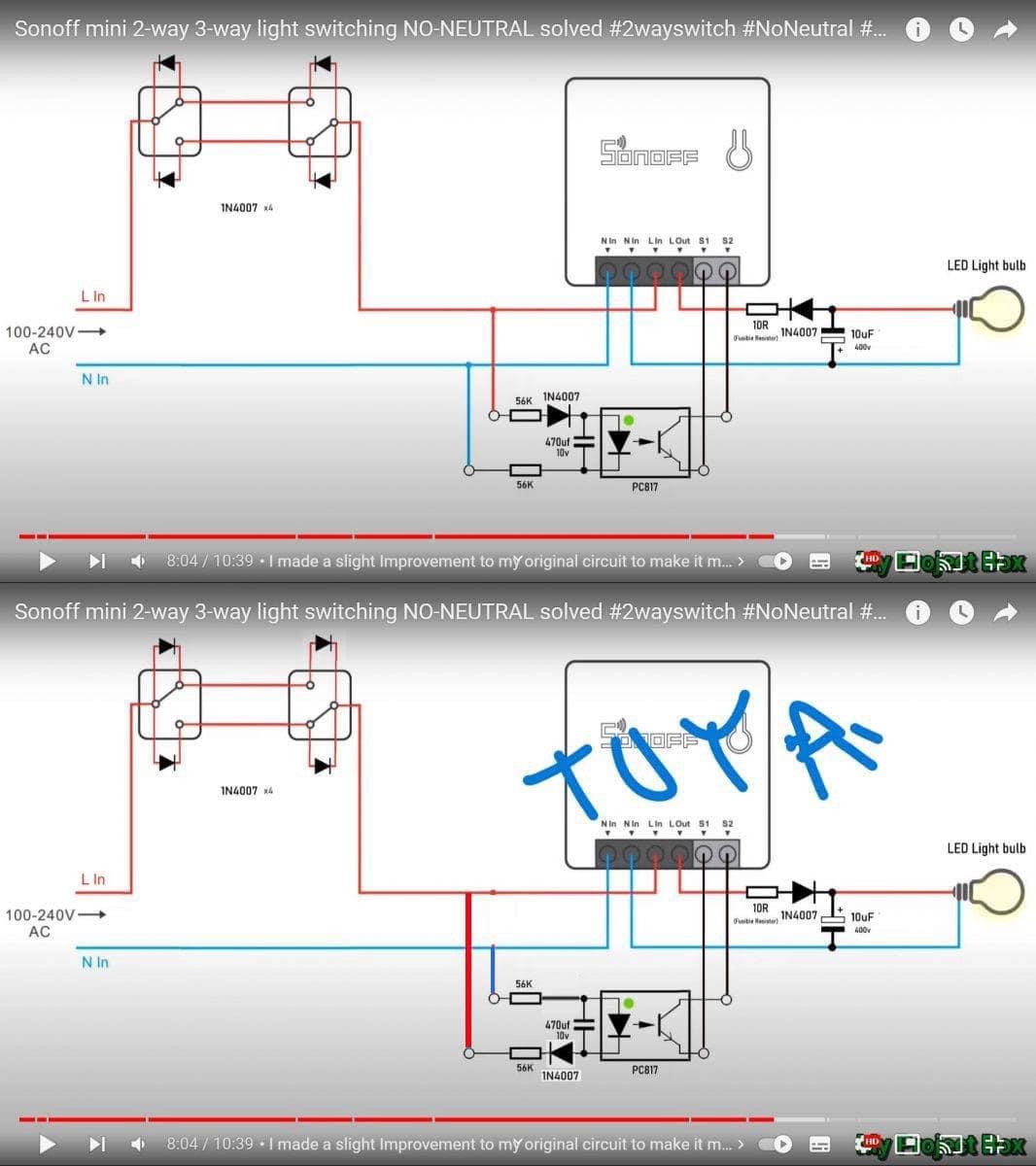
You can follow the exact same diagram from the video using sonoff mini, but if you’re using tuya mini switch you need to change the diode position & capacitor like this for it to work
Not that i “like” the concept, with extra capacitor, and additional relay , but anyways, IF i “locate” the Live and corresponding Neutral on the attic, i guess i can place another connection-box and “cut-in” on those there 
Don’t you mean LED Fixture rather than LED Bulb? An LED bulb would be DC which you don’t show in your wiring diagram. Since it’s AC the diode in the light circuit effectively reduces your LED fixture current in half. The Sonoff is switching the line voltage to the light, so what is the purpose of the diode/resistor/capacitor in the light circuit?
Using an optoisolator to the S1 S2 controls on the Sonoff is brilliant. I would use a larger capacitor to make sure the DC output is high enough to keep the Sonoff switched.
ON FURTHER CONSIDERATION- This won’t work. If you turn off the light at either of the three-way switches, then you are also turning off the power to the Sonoff, so it’s offline and you can’t control the light from Home Assistant.
I am really sorry, I use that diagram I got from somewhere as base for how to plan 2 way switches. As you can see, I haven’t done much diagrams, neither really asked about this stuff before.
I will take some time to map the cabling with my multi tester, although today my kid got sick so this will need to wait until the weekend probably.
Although, the main problem persist. I do not have any other L source in the second switch box to integrate the relay in the second besides the one coming from the Grey or black crossed cables.
Thank you very much for your patience  !
!
Im sorry didn’t read it all as it a long thread. As I understand you are trying to make smart two switches controlling one light?
Electricity in Germany is I believe the same as it is in Croatia.
So you probably have cross switch and that is why you cannot wire anything properly.
You will have to call electrician to rewire wires. For master switch you need live neutral and light wires and for slave live and neutral. That is how my electrician rewired my wires but i use smart switches. But I believe this should be the same.
Been there- done that.
Try drawing your problem that you want to solve. Put some space on your drawing that shows what is where. Also, which model of Sonoff switch are you using? Why do you want the Sonoff behind that particular switch?
BTW, in the US we call those “Three-way” switches. I have no clue why. Everywhere else in the world calls them “two way”. If I say 3-way it’s just from many years of doing electrical work in the U.S.
Was also my thought, that’s why i asked for his “solution/wire diagram” and not the one he had “seen” in YouTube
How ever you have some N and PE, so you could make a “dirty” solution, using 1 of them as additional L, (from same circuit as the first switch) … If you are so lucky they are the only connecting to each-other( meaning i.e the N/PE in switch-box 1, goes directly to switch-box 2 ( just mark it with a black/brown tape) so you dont forget ![]()
PS: If you hire an electrician, he/she will probably suggest the same, if he’s sane ( it already seems “c rowdy” in the tube, where the cables comes from
I am still trying to figure out what he has now. Then it would be easier to recommend a solution.
Agreed. Let’s understand what this is about exactly, before jumping into any recommendations.
It’s explained in the video, and yes you can toggle the relay even when the switch is physically turned off
I’m no electronic expect, but from what I understand, the diodes provide half wave dc when the physical switch is turned off, thus still powering the mini switch
Here’s a demo with my 2 way bathroom light switch (sorry the other door was locked but it does work as expected)

The mini switch with the octocoupler pcb installed on the led tube fixture and the diodes on each switch.

Neither am i( thou i did noticed the “rectifiers/diodes” on each switch), however im pretty sure a Certified Electrician would have to do some explaining, if suggesting such a change in someones electricity system, advantage vs dis-advantage , i.e
Powerloss ( meaning instead of saving electricity, for light bulps, you might just get out of it “even” if you are lucky), beside someone, somewhere did mention something about( Thou you might have to "switch on/off on/off, a couple of times, until the components !, “reacts” in correct order. ( meaning you are altering not only the components, maybe 3-5 times, you also altering the power through the cables, from “AC to DC, DC to AC, AC to DC” multiple times, to turn on/off your lights ( someone might get insane having to switch on/off 5 times, to turn lights on)
The Risk of having 2 such diodes in “every” switch-box( beside the relay and capacitor, somewhere along the “Road” .
The risk when altering the power in same cables( i.e “switch.on” now it’s 220V AC, “switch-Off” now it’s high-voltage DC), the risk/functionality of the equipment powered over such a “setup” etc.
To me it sounds/looks like that it’s simply not worth it !, not only “all” the extra work and components , and the power-loss, but also the Risks one is building into ones electrical system. (hoping/thinking it’s a “Solid” solution), im pretty sure this(your suggested solution) wouldn’t be approved by many Certified Electricians, in a common 220AC household system
Well you know, that’s just your opinion man, there’s always the other wifi relay that works with OPs existing wiring without additional wire/work.
Sorry, I could not respond later, sometimes life happens 
I had the time to check how exactly the current connection is working and I did this diagram (I hope it is clear enough)
From this diagram, I think the best backwards-not-smart-compatible way would be to make it like @boheme61 said and use the PR (GND) cable from BOX A to BOX B as an extra L cable so I could do something like this:
The device I want to use is this btw: https://sonoff.tech/wp-content/uploads/2022/12/说明书-ZBMINIL2-V1.0.pdf
I have added them to the first post too.
Pd: I know, my wiring diagram skills could be much better…
Anything would be an improvement. It’s a challenge to decipher what you have, but at least it isn’t a Fritzing picture. I won’t respond to a Fritzing picture.
You never did explain why the Sonoff has to be at the “B” location.
Here is what I think you have now.
Using this guide from Sonoff:

This should work with the Sonoff at the “A” location.:
I think there is something I do not understand here. If I connect LOut into the same cable that toggles S2 it will stop working after I turn it off one time remotely , do not? The S2 would not get any voltage change from the switches when LOut is off. At least that is what I though.
That is the reason why I wanted to put the sonoff with switch B, because there, the 2 way switchs will toggle the Live signal for the S2 input, and the sonoff will just toggle their last state each time it changes.
OK, I’ll bench test this today.