This is a work in progress but I’ve made some real advancements recently, so I thought I’d share.
Purpose:
I’m usually the hottest person in my house, so I tend to turn the heating off before bed. I’m often instructed, by the wife or kids, to go back down downstairs and turn it on, so I wanted a way to do this from upstairs.
My daughter’s bedroom is above the garage and I wanted to be able to check and control the temperature in the house based on her bedroom - the living room temperature varies loads because of the adjacent kitchen and front door.
Solution:
I found some projects where people were hacking in to their central heating programmers. I soldered onto the controller board so that I could use a raspberry pi zero to short out the ‘Advance’ button, which simulates it being pressed, so I can turn the heating or hot water on and off. I also used some GPIOs as inputs to detect if the LEDs were on.
I’ve made up some temperature sensors using ESP-01, a voltage regulator and a USB lead (I’d go for ESP-12 if I needed more because they’ve got the regulator built in)
Sensor Select lets me choose which of the sensors to use for controlling the heating. The Max and Min sets the threshold and there’s some automation behind that that checks if the heating is already on/off, so it doesn’t accidentally come on when it’s meant to go off.
I’ve also setup a Google Calendar, which I’m using to program a daily schedule. I haven’t fully integrated this yet since it’s too warm to have the heating come on at set times just yet. Best to get it sorted before the winter though!!
Next Step:
I can’t afford to buy loads of eTRV’s so I’m investigating a cheap way to make a plunger that I can fit on top of my existing TRVs. The end goal is to be able to control the radiators independently, so I can adjust things based on whether we’re upstairs, downstairs or if I want to be able to just warm my daughter’s room a bit and not have the rest of the house boiling hot!
If anyone has stumbled upon info to make your own eTRV I’d be interested to know. I’ve seen hacks to add WiFi to the basic one’s but their still pretty expensive.
A very interesting project. I have started at the other end with my heating and have 3 Energenie TRVs which I control through my Pi using their two way Pi-Mote and my own driver. Creating my own trv is a little beyond me, especially one that would look good.
I was thinking of using a z-wave device to replace my heating controller (which is identical to yours) for next winter, but I might be tempted to do this instead. Can you share more details, such as how you connected up to the controller, how you communicate from HA to the Pi-Zero, and how you powered the Pi-Zero.
Stripped from there are two specific resources I followed:-
and
If you do decide to go down this route, I’ll take the controller off the wall and take some pictures of the solder points. I simplified slightly by only having one ground and then just soldered to one side of the ‘Advance’ switch and LED. What you can see in the tutorials is basically a transistor’s pins soldered either side of the advance switch and the gate pin attached to the RPi GPIO. By setting the GPIO pin high then low, it opens the gate on the transistor and the current jumps across the switch, exactly as if the button had been pressed. I’m not an electrician but it was fairly straight forward. The hardest bit was closing the back on the controller with the various wires! The LED is odd but basically there’s a solder pad on the board of the controller. You can measure 3.3V when the LED is OFF. Here’s the HA code for the GPIO pins
# Central Heating LEDs
binary_sensor:
  platform: rpi_gpio
  ports:
    5: HW LED
    22: CH LED
  pull_mode: "DOWN"
  value_high: "on"
  value_low: "off"
  invert_logic: true
  bouncetime: 50

# # Central Heating Switches
switch:
  platform: rpi_gpio
  ports:
    26: Central Heating
    4: Hot Water
I’ve got a script that turns the switch on, waits 1 sec, then turns the switch off, otherwise the GPIO pin would be left high and it would be as if the Advance button was being held down on the controller.
The power for the RPi is from a USB plug that I dismantled. The 3.3V on the controller board didn’t have enough current to run the Pi and power the display, so I tapped into the 240V input. That part was scary I must admit but I obviously turned CBs off to take the controller off and tested solder points with a multi-meter for continuity rather than checking everything with 240V plugged in.
As for communicating with HA. This is running on the PiZero that is in my ‘PiStat’. I’ve set up Samba so I can easily adjust config etc.
P.S. thanks for commenting on my post for ‘A switch that does nothing’. I’ve got Input Booleans setup to choose which temp sensor to use
I think you’re onto a winner there, if I’d have known about esp boards when I first started I’d definitely go down that route. If you want to be able to control both heating and water, as well as monitor their condition though you’re going to need 4 pins. There’s esp-12s on eBay for about £2.50, although it wouldn’t hurt to prove the principal with the esp-01 you’ve got.
I’ll find some more details about the components I used tomorrow and post them here.
I put a 4.7k ohm resistor on the transistor gate pin going to ground. I’m not sure if I needed to do that with the RPi because of the internal pull down setting on the GPIO but I’d recommend doing that with the esp, just to make sure there’s no residual current going to the gate of the transistor when it’s not in use, as this will keep the transistor open.
Like I said before this was completely new territory to me and I’m not sure what your electronics knowledge is like, so apologies if you know this already.
Thanks. I’ll get the parts. I have another few projects that I want to do first - I should only need this for next winter - but it is definitely on the list.
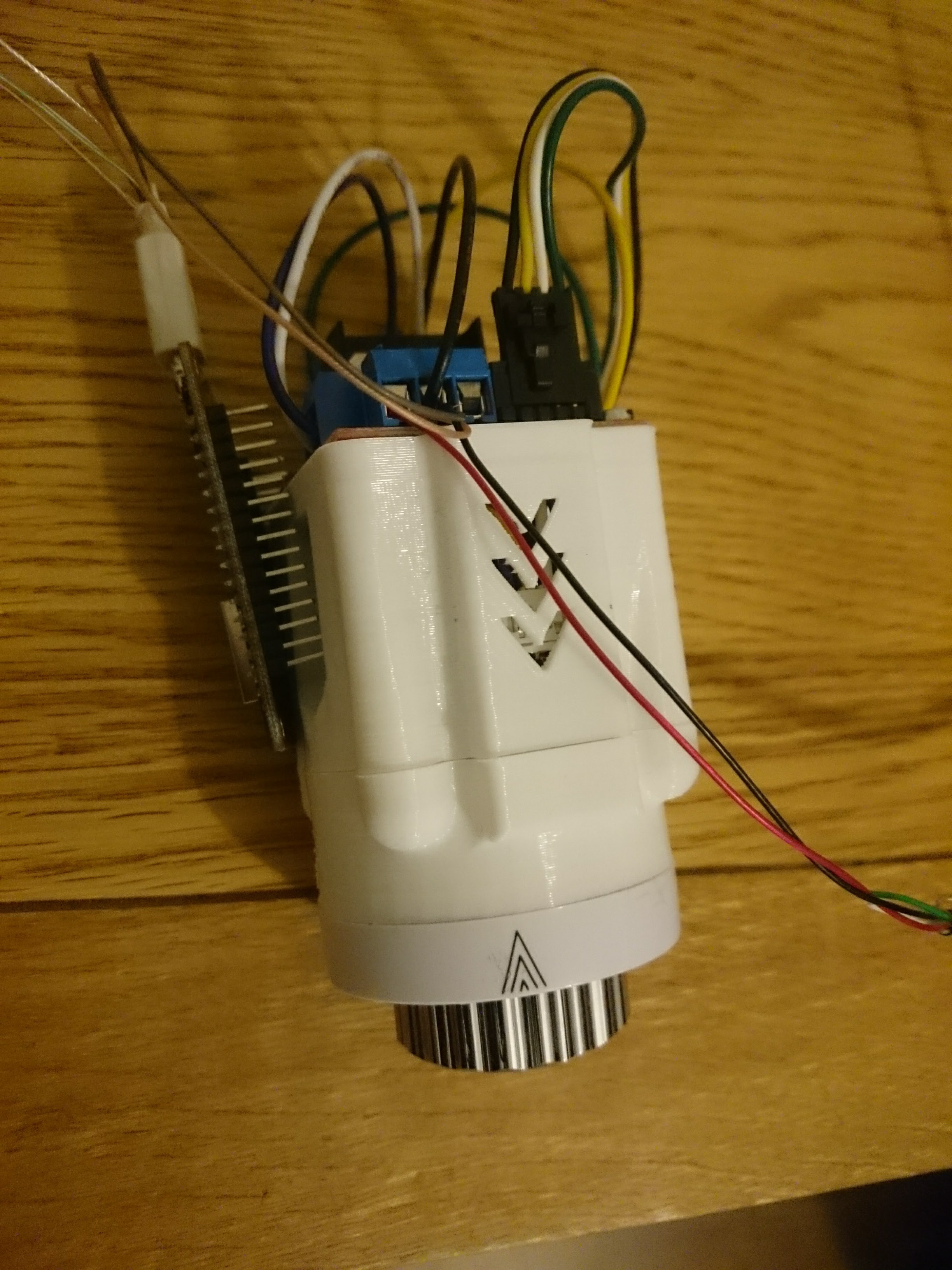
I’ve been making some real progress with this eTRV. Here’s a picture of the prototype with a 3D printed housing and the attachment part of a standard TRV. I’ve managed to connect this to HA and I’ve got a cover that I can use to operate the plunger. I’m going to get the mechanical part of the valve next week, so I can adjust it and make sure the pin extends to the correct position.