I have a question. Can I also measure negative current with PZEM-017? I would like to measure the charging and discharging of a battery in a solar system with it.
Hello, it’s not like INA22x, it measure current/power only one way. Thus is useful to measure energy from PV panels, for example.
Just read the manual ![]() https://thesunpays.com/downloads/files/Battery%20SOC%20meters/PZEM-003%20017User%20Manual(MEDC300V).pdf
https://thesunpays.com/downloads/files/Battery%20SOC%20meters/PZEM-003%20017User%20Manual(MEDC300V).pdf

I’m using this power monitor with modbus integration, because haven’t found a way how to use this integration with RS485 adapter without automatic flow control, like standalone MAX485. It requires flow_control_pin. Any suggestions?

EDIT:
I’ve got it…
# ESP32     MAX485  PZEM-017
#
# GPIO10    DI
# GPIO20    RI
# GPIO21    DE+RE
# GND       GND     GND
# 3V3       VCC
# 5V                5V
#           A       A
#           B       B

uart:
  baud_rate: 9600
  data_bits: 8
  stop_bits: 2
  parity: NONE
  tx_pin: GPIO10
  rx_pin: GPIO20

modbus:
  flow_control_pin: GPIO21

modbus_controller:
  address: 30
i try to coment on patreon and i have to pay to do so so bad advertising
Did anyone has checked the accuracy of Pzem 017?
I’m using it with 50A shunt to monitor my solar installation in real time. And yes, I have programmed pzem 017 to use 50A shunt too. I have a mppt charge controller which also display on its screen the realtime voltage, current, power and kWh for the day. My setup has max current of 18.5 A, max voltage around 96V seen so far from panels.
The charge controller and pzem 017 kWh readings have differences. For production above 5 kWh, I have seen a difference of 4% (pzem 017 overreporting by approx 4% or charger underreporting by 4%) but below 2kWh, the difference is huge (pzem 017 overreporting by approx 25% or charger underreporting by 25%).
Pzem 017 claims to be accurate to 1% but without actual accuracy it is impossible to blame pzem 017 or mppt charge controller.
I don’t have a constant dc load on pzem 017, so I would like to know if someone has done some accuracy tests.
Here’s my approach to make it “natively” wireless ![]() GitHub - taHC81/pzem017-wireless: Built-in wireless functionality with ESP32-C3 and ESPhome
GitHub - taHC81/pzem017-wireless: Built-in wireless functionality with ESP32-C3 and ESPhome

esphome:
  name: pzem-017

esp32:
  variant: ESP32C3
  board: esp32-c3-devkitm-1

wifi:
  networks:
  - ssid: !secret wifi_ssid
    password: !secret wifi_password

api:
ota:
logger:

uart:
  baud_rate: 9600
  data_bits: 8
  stop_bits: 2
  parity: NONE
  tx_pin: GPIO10
  rx_pin: GPIO20

sensor:
  - platform: uptime
    name: "PZEM-017 uptime"
    update_interval: 30s
  - platform: wifi_signal
    name: "PZEM-017 WiFi Signal Sensor"
    update_interval: 30s

  - platform: pzemdc
    address: 30
    current:
      name: "PZEM-017 Current"
    voltage:
      name: "PZEM-017 Voltage"
    power:
      name: "PZEM-017 Power"
    energy:
      name: "PZEM-017 Energy"
    update_interval: 2s

switch:
  - platform: restart
    name: "PZEM-017 restart"

text_sensor:
  - platform: wifi_info
    ip_address:
      id: ip_address
      name: PZEM-017 IP Address
    ssid:
      name: PZEM-017 Connected SSID
1 Like
Remove that QC past sticker ![]()
![]()
![]()
1 Like
Hey Sam, can you share a diagram or some knowledge on how to wire to get it working for monitoring direct solar panels
I managed to fry 2 units , I give them power from the USB port but I think this is not ok if you don’t have a special power brick or something ,give up ![]()


How many ohm capacitor you replace for r3 and r5? Tks you
Hi, they’ve been burnt, so replaced with a same 10R (10 ohm). And these are resistors, not capacitors ![]()
That looks like a failed USB adapter, there’s a protection diode U6 to avoid mismatched + and - on USB, so it might be overvoltage. Or incorrect connection on a shunt side.
Hi All,
I recently built two DC energy meters using the PZEM-017, RS485-to-TTL converter, and ESP8266, one for a solar system and another for a DC battery system. I ran into several issues during the DIY process, but I eventually got everything working. It has now been running smoothly for a week without any issues.
Here’s the blog post I wrote about the process. Sharing it here in case it helps someone in the future:
Direct link: https://developerinsider.co/solar-battery-dc-energy-meter-for-home-assistant/
Web archive link: https://web.archive.org/web/20250802161032/https://developerinsider.co/solar-battery-dc-energy-meter-for-home-assistant/
2 Likes
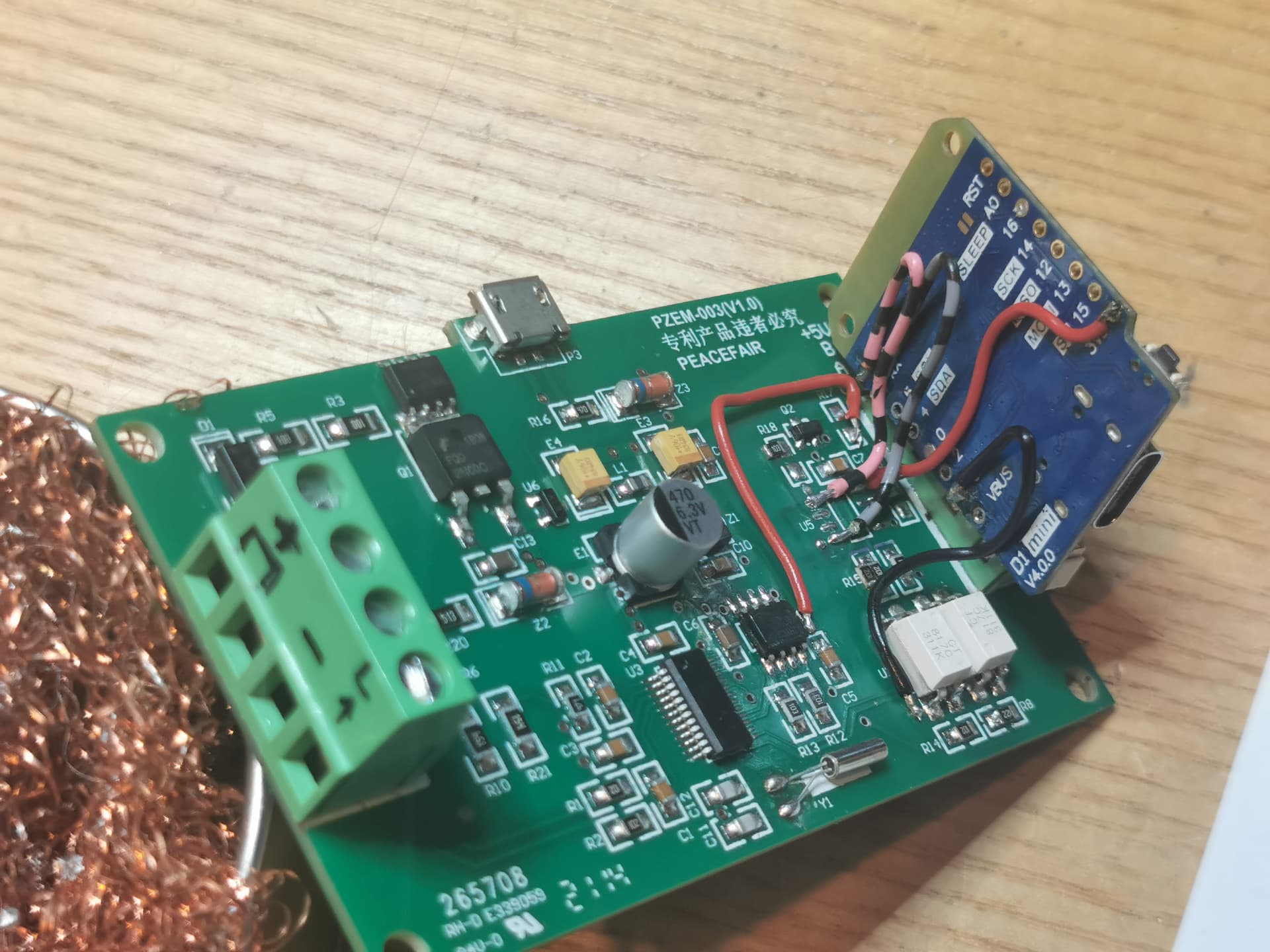
Here is my setup after 3 hours of digging why it does not work.
I hole this will contribute to the general knowledge and helps somebody.
Components:
- PZEM 003 v1 (similar with PZEM 017 but only 10A)
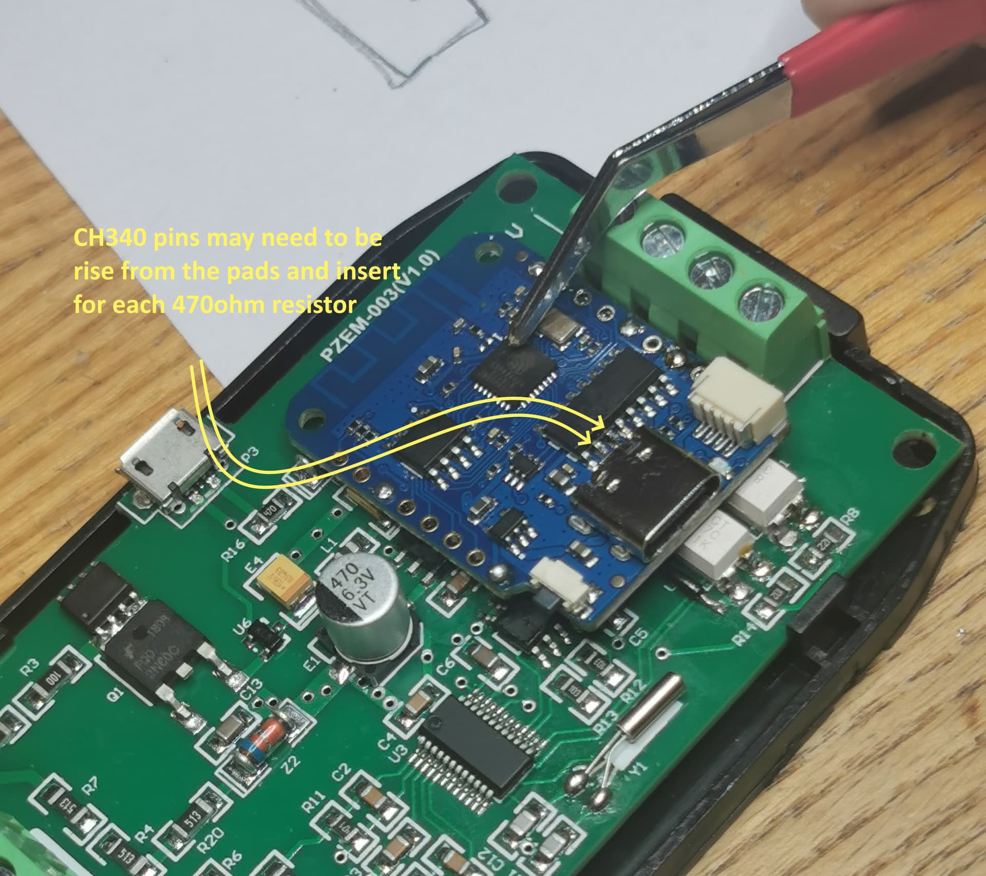
- Wemos D1 mini v4 with CH340 usb-ttl
- Tasmota
I have read somewhere while trying to find the issue of communication, CH340 creates issues on serial because of the schematic and 470ohm resistor should be inserted
(Can't get PZEM-004T v3 with WEMOS D1 Mini Pro working · arendst/Tasmota · Discussion #18170 · GitHub)
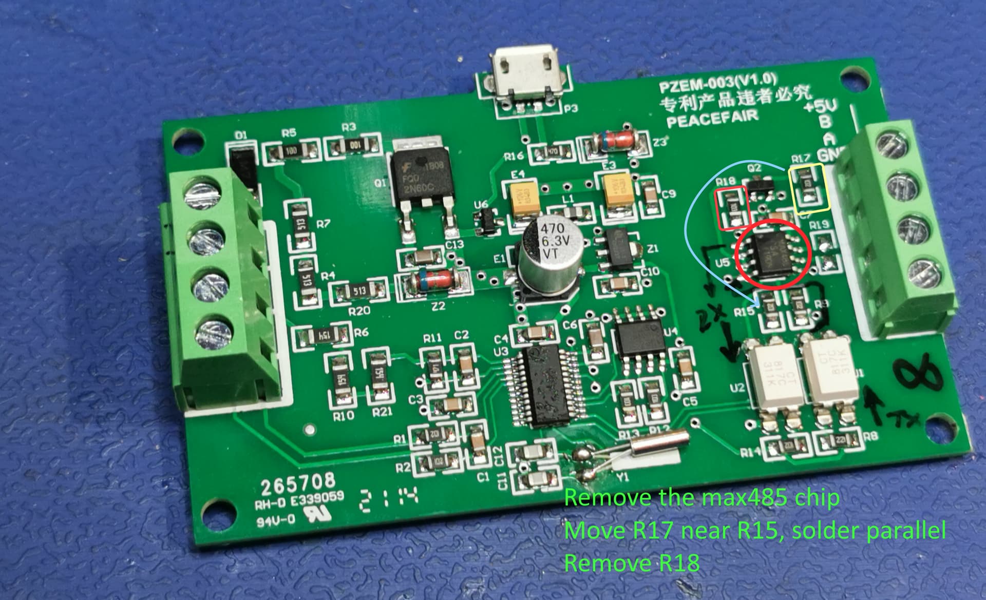
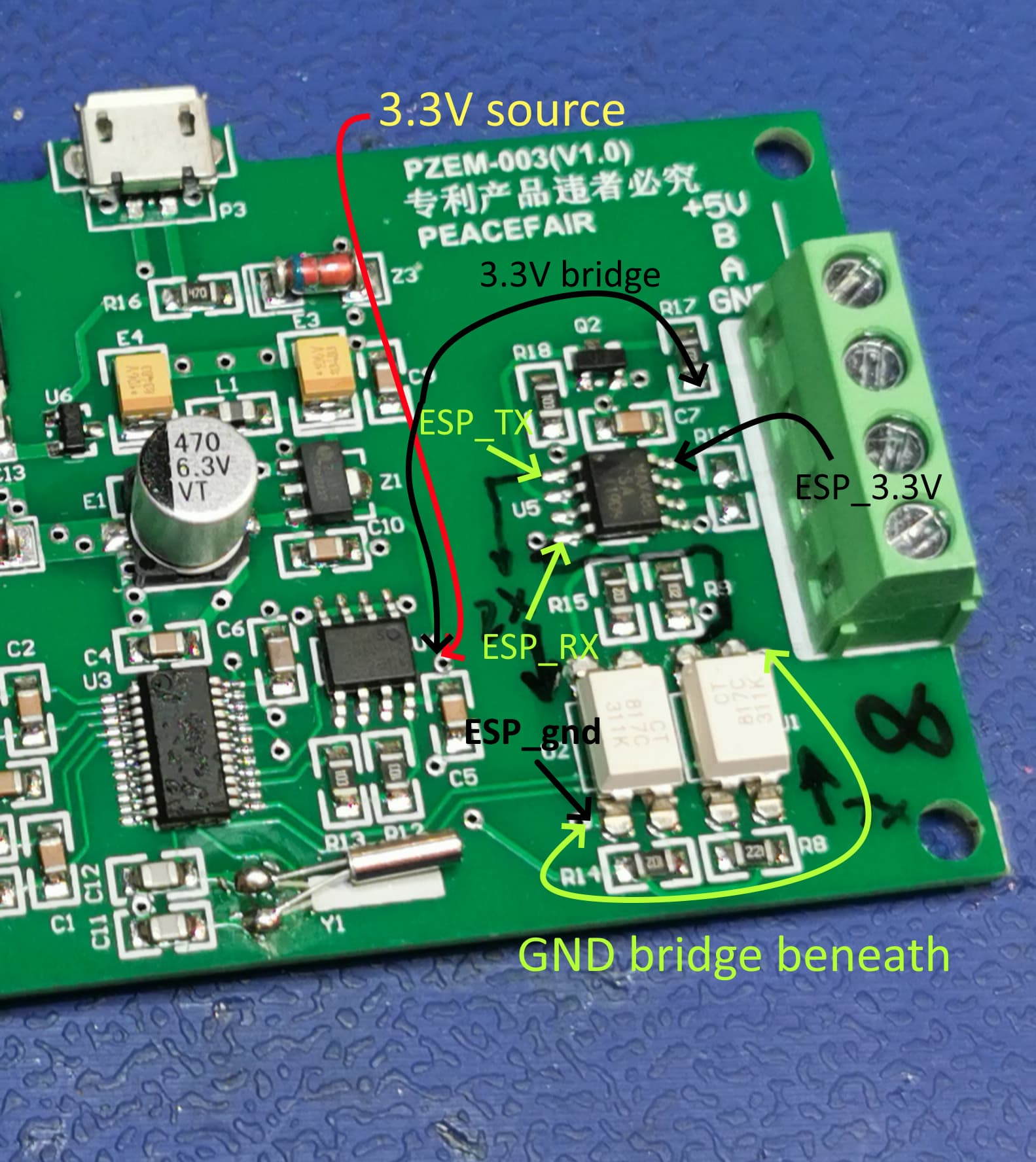
Moving of the R17 parallel with R15 is intended to assure the opto U2 works with 3.3V.
The original design is for 5V.
Do not forget to solder the GND bridge under the pcb.
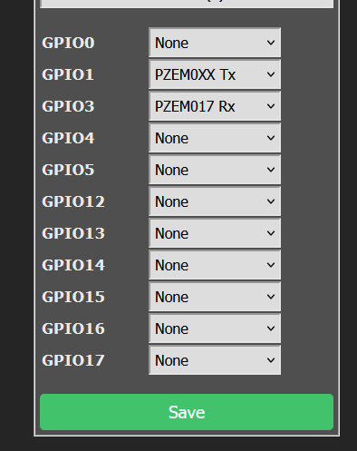
Tasmota settings:
Set up the GPIO:
GPIO1 - PZEM0xxTX
GPIO3 - PZEM017RX
In console type “Moduleaddress 1”, for the Tasmota to assign the current communication device to address 1.
WARNING !!.
The primary power regulator built on PZEM is very primitive, based on heat dissipation.
(diode D1 for reverse polarity protection, resistors for dropping the current, transistor MOS(!) and zenner diode in the gate for limiting the output voltage at 8-12V)
Adding an ESP to the load cause the thermal acceleration (50V, 80mA total) till the soldering joints melting (few minutes).
So a separate power source is advised to be used on AC>USB (or other variant DC/DC buck), be aware to use ISOLATED power source or not needed isolated if the power source is the same with the measured one (and remove D1 to avoid consuming useless power and dissipate heat).
Keep in mind to avoid ground loop on the negative side because of the shunt.
(you cannot see it until you draw the circuit on the paper and probably the colleague with burned PZEM encountered that ground loop)
In my application I want to monitor the power/energy consumption of the automation stuff connected directly the 48V battery for backup purpose ~max 200-250W capability (buck DC/DC 70V>4USB to Solar Assistant rpiZero, Home Assistant OdroidC2, power diverter ESP32, network switch + I intend to bring 48V to the POE/Server/router cabinet)