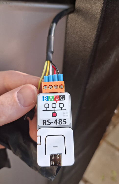
That cable and plug is coming out of my iStore alongside the power cable. I haven’t opened it up to look at the control board, but the terminals you have pictured (A, B, Red and black) look like the Modbus outlet. That should be all you need.
But the RS485 should be connected via yellow and white. If you have wired that plug for the Modbus outlet you need you change over the cables or you might overload something with a wrong connection. Red should be the 12+ and black should be connected to the ground. It looks like you have got the connections right but the colouring you have used will cause confusion later.
A+ on the control board will then connect to the A on the RS485
B on the control board will connect to the B on the RS485.
It looks ok - just using the wrong colours.
The RS485 can run on 5V but I took a 3.3v volt feed from my ESP32 just to give a margin.
EDIT: Now I look closer - you appear to be powering your ESP32 from the USB connection AND you are feeding the 12v from the HWS to something. If you have 5v into the ESP, it can power the RS485 - you don’t need both.
Or is the 12v feeding into the black thing that then feeds the ESP and RS485?
I stuck with the original 99 and that worked for me - after I had fixed a dry solder connection (all my own work!). Check all your connections with a multi-meter.
My iStore 270L (with r290) was installed in April so I assume would be similar to yours. I’m surprised the 99 doesn’t work, because I assumed the boards and firmware would be very standardised.
For everyone to know, my unit isn’t the r290 and no communications is built on to the board. They didn’t even know what that RS485 port is for. I purchased my iStore 180L on 11th March 2025 and my simple request from them was in my email to them was “IT MUST HAVE WIFI” to which they replied with it will, just no app to control it with" I wish I never purchased this and went to a superior Midea system. I’ve got my own custom esp32 controlling it and its so good with HA
My HWS doesn’t keep time very well. It seems to lose minutes over a month, so my timer is out.
Using your template, I set up a sensor to see what the system time is, so that I can adjust it when it is too far out. (Similar to the reporting/display on the timer setting).
However, it only seems to report the system time haphazardly. Any suggestions?
Managed to fix it and find the actual board. Do you have top and bottom tank temperatures? I get N/A but I can turn on and off the unit - I got the 180L system and I got a proper wifi module as well which has the temperatures
Steve, I’m assuming you’ve done something special to get the top and bottom tanks temperatures? Like wrapped an Arduino temperature sensor around the discharge pipes??
The iStore 270 has sensors for those readings. The top and bottom tank temperatures are available in the modbus register, so I just followed the code outlined above to read them.
Sorry I don’t know what the wifi box is reading, so I can’t offer any insight. Mine is a different method that reads directly off the control board.
All good Steve, I managed to figure it out at 2am this morning. I had DE and RE not tied together going to GPIO 4, as soon as I did that it worked instantly
Hey guys, just doing the same thing now to my iStore 270. Im going the atom route to avoid using a buck converter.
This plug you pictured here, is that what is on the istore as stock to connect to rs485? I have my atom etc on order so just need to figure out what connectors I need to get to wire it into my HWS.
Thanks
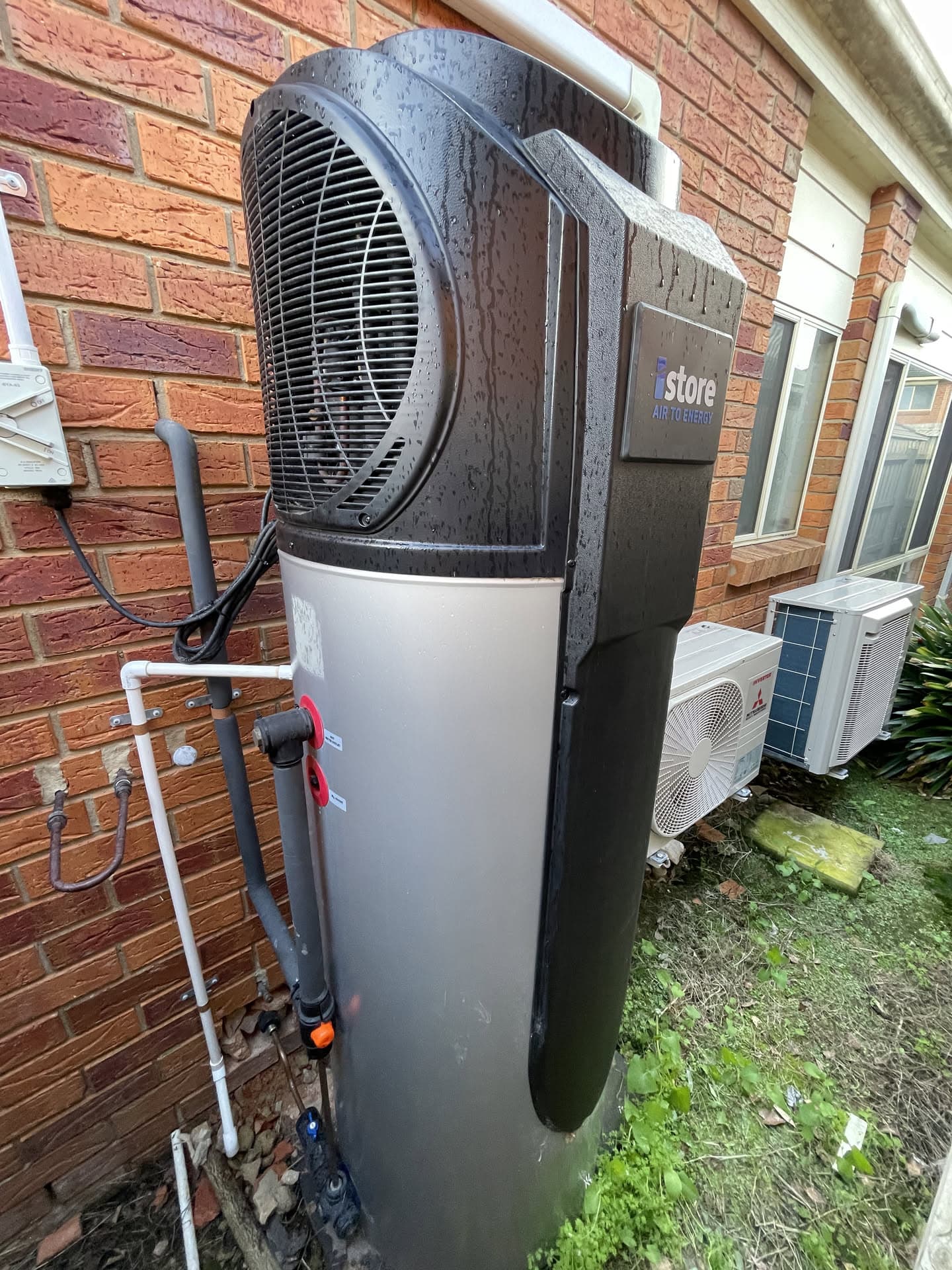
This is the mass of wires I have coming out of what I assume is the controller on my istore 270. I took the zipties off and could not find that connector in your photo anywhere easily.
My plug comes out the side of the system alongside the power cable. It is wrapped up in some heat-shrink (which has not been heat shrunk!) I did not have to get into the case at all.
No need to touch those cables. Remove the panel containing the unit control panel, and you will find the cable you are looking for. It will have a connector on it. I used a paper clip to remove the pins from the connector and put them under the atom screw terminals. This picture from above should give you some idea where the connector is.
Are you talking about the touch screen on the front of the unit? I took that out but couldnt get it apart easily. there is only 1 cable/connector going into it. You can kind of see it in the right hand side of my photo, its a white cable in the darkness. Thats the back of my touch-panel.
If you have some photos around the are thatd help massively, I got a suspicion that mine is different. I dont see any plastic moulding looking like your photo (close though). I took the large front panel off holding the controller, and I saw nothing there. no diagrams just the single white cable i mentioned before that leads into the Black box in my photo.
I think if that larger box is the controller in my original photo, ill need to remove the entire top cover to get access to it.
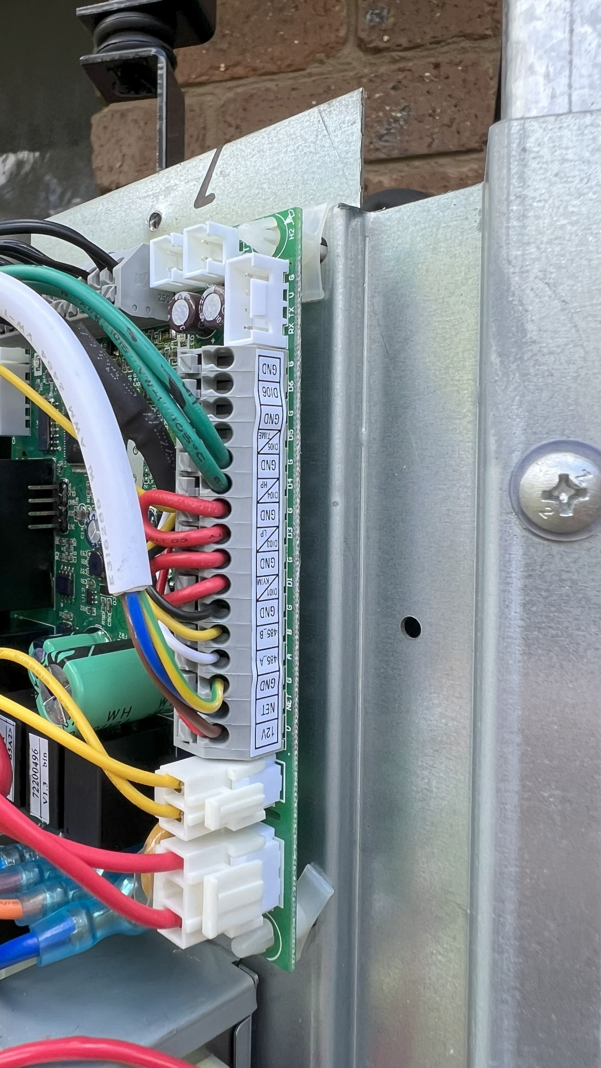
Yeah, I have an EVO Heat 270 looks similar, but if you can’t find a connector behind the large front panel holding the touch screen, then I think you are going to have to go digging. I remember having to remove the top to get access to the main controller. Here is a picture of my control board with the cover off.
Massively helps.
Thats exactly what I suspected was going on. I figured the front panel was nothing but a basic interface to that big controller. I’ll have to take the top cover off and access that main box to get access to that terminal strip. Assuming its the same strip, I’ll just run my own wires into it for the atom. I’ll report back with my findings once the parts arrive.
Thanks mate.
Hi mate, was wondering, what esphome yaml are you using for your iStore270 now? the one in the github linked earlier? or something else? just going through the code now.