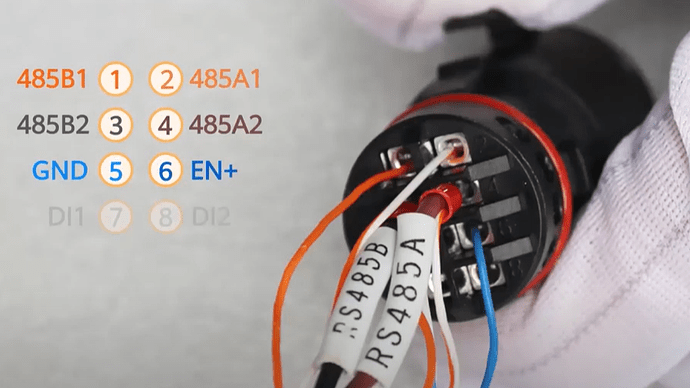
My RS485 is connected to a smart power meter module. Can I connect the USB to RS485 in parallel at the inverter side?
The smart meter and battery should be connected to the RS485A2 and RS485B2 pins of your inverter (pins 3 and 4 in the case of my SUN2000-3KTL-L1).
The RS485A1 and RS485B1 pins should always be available on your (primary) inverter. In the case we’re you have multiple inverters that are connected in cascade the pins are used on the secondary inverters to connect to the primary inverter.
Hi Thomas,
I have an M5 Atom RS485 lying around that I want to flash with a modbus bridge to test this scenario. I know that some people are already using a commercial RTU-to-TCP bridge together with my integration 
Ok, tnx a lot! Any pictures of the connector by accident? I’m on holiday right now. I have a 4,6ktl-l1 and didn’t know there were multiple rs485 pinouts.
Edit:
Picture:
I guess I can use RS485_2 if my installer already used RS485_1.
The numberings of your screenshot are a bit confusing, but looking at the installation videos is an excellent idea:
Excellent tnx. I guess choosing A1+B1 or A2+B2 is no problem (in case my installer used A1+B1 for connecting the smart power meter)?
Great work! Thanks. Does anybody know if this also works with 2 cascaded inverters? As far as I understand, in a cascaded scenario, the RS485A1 und B1 pins are used to connect to the cascaded second inverter. Any insights would be highly appreciated!
Ok, so with this last update I lost the communication I had before Tried everything and not able to connect … I have ordered a usb pen drive but i have a question (might be silly) the usb pen connects where? On the Pi?
In my case, the installer had connected the power meter to pins 1+2, and the battery to pins 3+4. While that was a valid installation method for older types of inverters, it is no longer the case. After a firmware update of the inverter, the power meter stopped working. I followed the following guide to fix this issue: Power Meter is Abnormal after the inverter is upgraded .
This meant that I had to crimp the RS485 wires of the power meter and battery together to fit in the slot for pins 3+4. If you have a correctly setup installation, pins 1+2 should be free (if you have only one inverter in your setup).
Tnx for your great explanation! Is it possible to switch from AP mode to serial mode or do I need to readd the integration?
You need to delete and re-add the integration.
Hi everybody, thanks to this integration now i can read my system sensor.
I have a SUN2000-6ktl-L1 running firmware V200R001C00SPC119 with SDongle WLAN-LE running firmware V100R001C00SPC129.
I set up the parameters in the inverter as described.
For the integration setup:
- IP of inverter 192.168.107.xxx (ip of my home LAN).
- Port 502
- Slave 1
192.168.107.xx is ip of the dongle not of the inverter, which is in the subnet 192.168.200.x usually 192.168.200.1.
Any screenshot of 1 or 2days data would be good enough indication that this method is working fine and is the best method in case we go along the networking route instead of serial route.
that converter is too expensive, compared to a old used or even low end router which are compatible with OpenWrt / DD-wrt.
When logged to inverter AP during configuration, in settings>Communication configuration>Router settings
you read the INVERTER ip address that the home router has assigned to it via the ethernet link, obviously via the SDongle.
The subnet 192.168.200.xxx is the LAN created and managed by the inverter that acts as gateway and DHCP server at the IP address 192.168.200.1
But in a configuration like mine, the SUN2000 is only a client of my LAN, with an IP assigned by my router as the other clients.
By the way the important is it works!!!
About the data, my Huawei setup is only a retrofit of an enphase system. In Italy enphase batteries are not available so, as retrofit, I installed the Huawei system with the SUN2000 receiving energy in the AC side by enphase for charge/discharge the battery LUN2000, it is not linked to the solar panels.
The only relevant data are the ones from the battery.
If you dig the internet a bit, you’ll find them at around 7 euros/USD.
I agree that if you have an old DD/Openwrt compatible router, with the suitable capacities, it’s good to use it. Still, the RS485 way is probably the most reliable approach.
I do have a PLC engineer friend, I think he might be able to source HF7211-0 RS485 for me. Let’s see.
Yes it is still working via wifi and the PI. Important to place the options as DHCP if not you do not have any communication
Obviously, it will work, if you place your rpi4 running HA near the inverter. Which is not possible for everyone.
I think the more methods we have available easier it will be for users to integrate these inverters into HA.
The latest method is the rS485 connection, either wired or wireless using RS485 to wifi devices.
Yes just making people aware that this small setting might cause a problem, It did for me and it was an easy fix.


