I got both. Installed OpenSprinkler on a wemos and command with it the hunter.
1 Like
Indeed, this worked also for me. Thank you!
Hey mate, do you know where I can find the complete idiots guide to this project? Its something id like to try but Im not sure where to start.
EG: wiring and how to compile and upload to the ESP
Hi,
I wrote no code, the opensprinkler port was made by seb821, I just adapted it to my needs.
The main differences are Wemos pin configuratio adapted to my already wired MCU (I previousy used ecodina’s FW to expose REST API) and NTP update every 30 mins (this to solve the losing of the current time in case of power failures, lack of RTC and my dad that frequently disconnected the Hunter to manually using the well pump)
Device Used: Wemos D1 mini
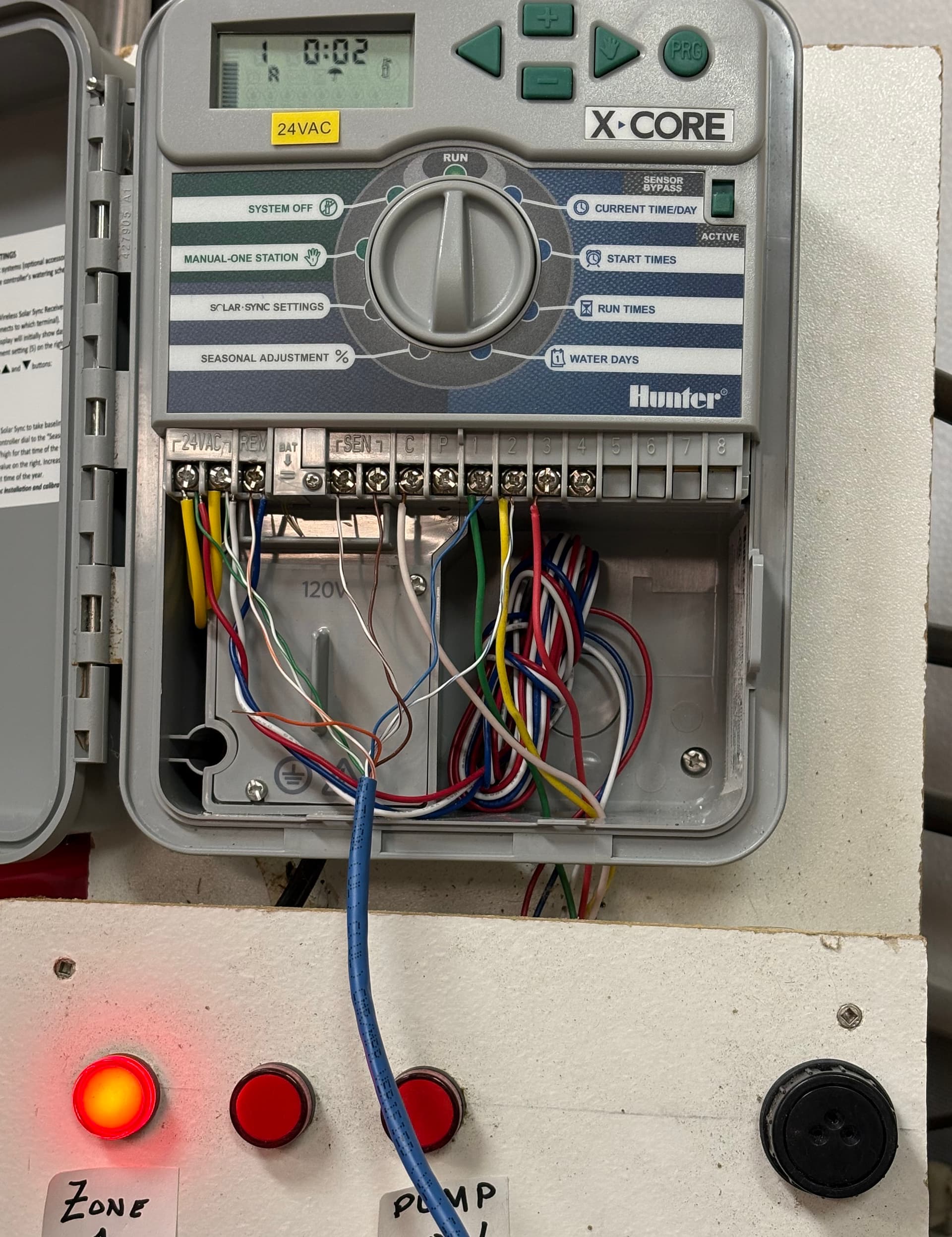
Wiring: as depicted in this picture:
GND to one of the 24VAC terminals, GPIO16 (D0 pin for Wemos D1 Mini) to REM terminal of the Hunter.
FW: I used a linux laptop and used these commands
sudo chmod 666 /dev/ttyUSB0   #because I'm lazy and struggled to solve permission problems on my laptop
esptool.py --port /dev/ttyUSB0 erase_flash
pio run -v  -t upload
Then wire it as described and power it up via USB. The Wemos should start his own AP for initial configuration.
The Opensprinkler FW is a little old but it works for me. It has API for HA integration, rain forecast from OS and web interface for programming.
The Hunter has been set to OFF all the summer this year, but I chose to keep it as it is because, if needed, I could simply turn the knob to do one off programs.
Thanks for the quick reply. So a couple of dumb questions.
- What file do I use to flash the ESP?
- Can I use a buck converter to power the ESP?
Amazon.com
- published a release on the repo with my binary, if you trust me.
https://github.com/wrongisthenewright/OpenSprinkler-Firmware-Hunter/releases/download/v1.0/firmware.bin - no idea, I’m an IT guy not an electrician

1 Like
Just want to say thanks mate. Got it all up and running.![]() I’ll see how it goes over the next few days.
I’ll see how it goes over the next few days.
How hard would it be to update to the latest version of open sprinkler? Is it just a matter of grabbing the latest files and add the hunter .h and CPP files?
Not so simple, I’ve looked into it but is waaaay over my possibilities…
Thanks anyway. Your help is much appreciated
I was able to create an ESPHome component using all of the info I got from here. I haven’t had the chance to test it yet, but it looks promising.
Thanks everybody
I built the component, but haven’t had the chance to test it yet. If you want to give it a try I can share the code with you
Javier,
Wish I’d checked here before sending you an email.
While things are getting crazy before Christmas, I’d love to try to help you get this working.
I’ve done a couple ESPHome projects, though I have never written a custom component. I happen to have an X-Core available for testing on my bench along with a scope to look at the signals going over the smartport. Just have to get my ROAM transmitter/receiver working - they’re not quite behaving properly at the moment.
1 Like
Javier - Seems they’re working when I’m close enough. I’ll start by getting some signal traces of “real” ROAM messages to the REM pin.
1 Like
wrongisthenwright - For your 2nd question, I’ve used buck converters successfully on other projects with 24VAC power sources. Just make sure that (1) you put a full rectifier in front of the converter and (2) you do NOT connect the converter output to the ESP until you’ve dialed it down to 5 or 3.3V.
The converter I use (LM2596S) happens to have a capacitor on the DC input, so none is needed after the rectifier.
Do note that the DC IN ground is often connected directly to DC OUT ground. So, you might want to investigate using an opto-isolator or other output circuit to drive the REM pin if it involves a different ground.
Were you able to deploy my GitHub project with no issues?
I didn’t think it was a ready-to-go project. Of course, it doesn’t compile right away as there’s no secrets.yaml file in the folder.
And, I’ve got a couple 8266 D1 modules around, but no ESP32 ones.
I’ll doctor up the file for my location and see how it goes. This’ll be the first time I’m using a custom component, so I hope there’s nothing I need to add or a special place to put code.
OK, made all the YAML changes for my environment and it does compile.
Now, I just have to go wire this thing up.
My primary intent is to be able to monitor when my plants are being watered. Turning the system on & off is secondary, but desirable – hence the interest in this project.
I may wire this to a dummy REM circuit just so I can confirm the basic bit banging to send the messages. After that, I need to do some more interface work.
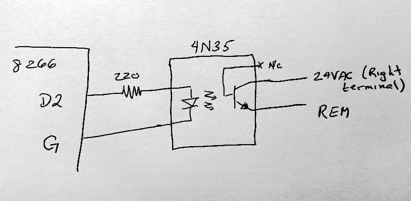
I am very leery about connecting the 24V power and REM pins directly to the 8266.
I think I’ll play a bit with it and use an opto isolator to get some protection as I expect to be powering the D1 mini with a buck converter connected to the 24VAC terminals. The buck converter I use has the input DC ground connected to the output DC ground. Not quite sure how that is going to work out if I put in a full bridge rectifier and the ground “bounces” between the two AC power inputs. Alternately, I may use a half rectifier and have the ground side be the middle AC pin which folks are connecting directly to the 3.3V D1 pin.
If you have any thougts on the best way to interface this device, I’d love to hear it.
Later, I’ll add a bunch of sensors to read the actual Z1-Z4 outputs. I want my device to monitor irrigation, not just control it. Finally, I need some way to confirm that there is water pressure so I know that the plants are actually getting water when the valves are activated. (My HOA often turns the pump off for maintenance or when it’s been rainging a lot)
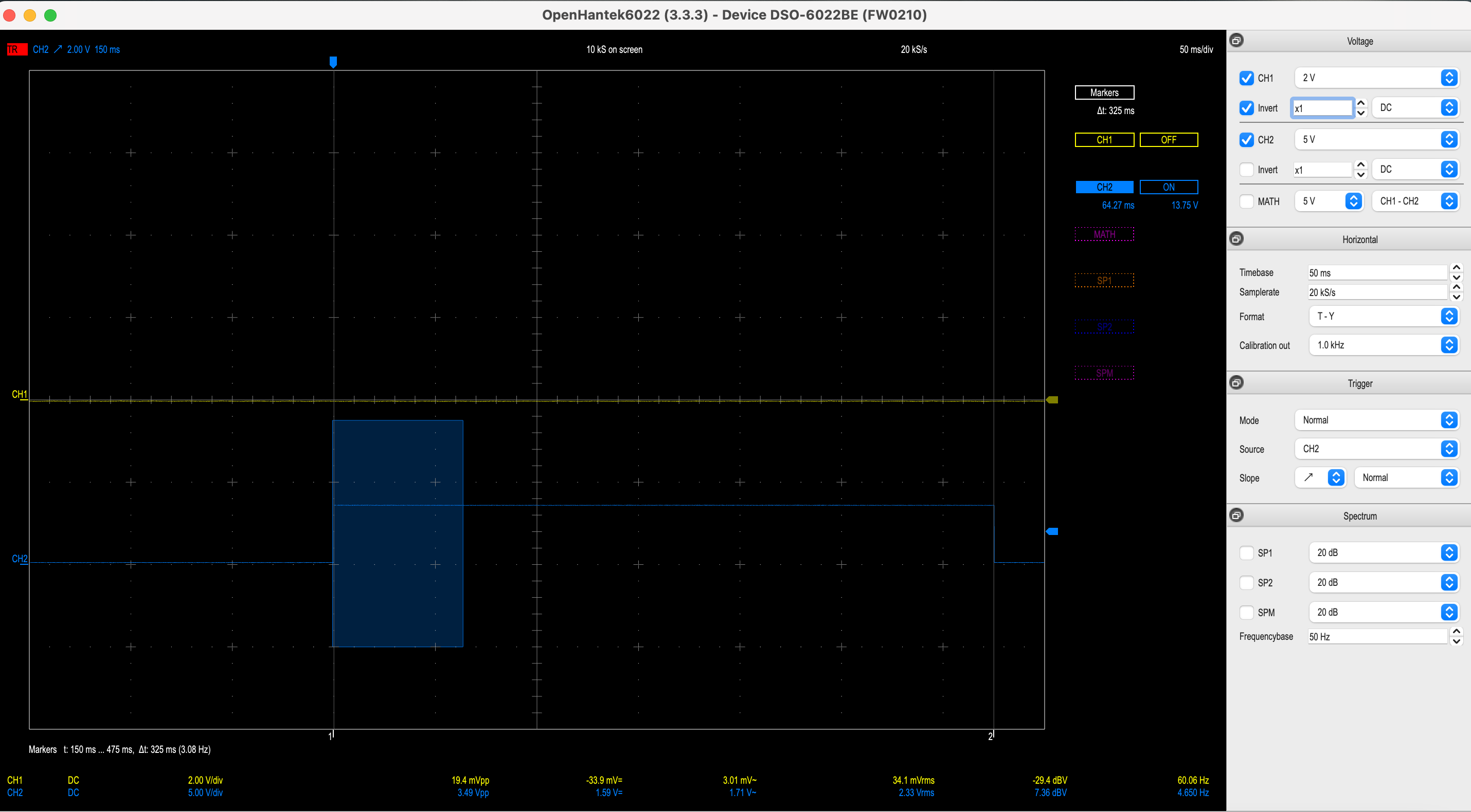
Had a few minutes today, so I hooked up an 8266, loaded the yaml and did some quick timing checks. Good news so far:
- Starting pulse is 325 msec
- Next pulse is 60 msec
- Individual data pulses are very close to 2msec overall with 200 usec for the narrow pulse, leaving 1800msec for the wide part.
This looks to be doing exactly what the code calls for and matches what I get with a real ROAM controller.
Since I haven’t interfaced this to the real REM pin, I can’t say it’s working for real.
Trace with opening two pulses
Zooming in on the individual bits…
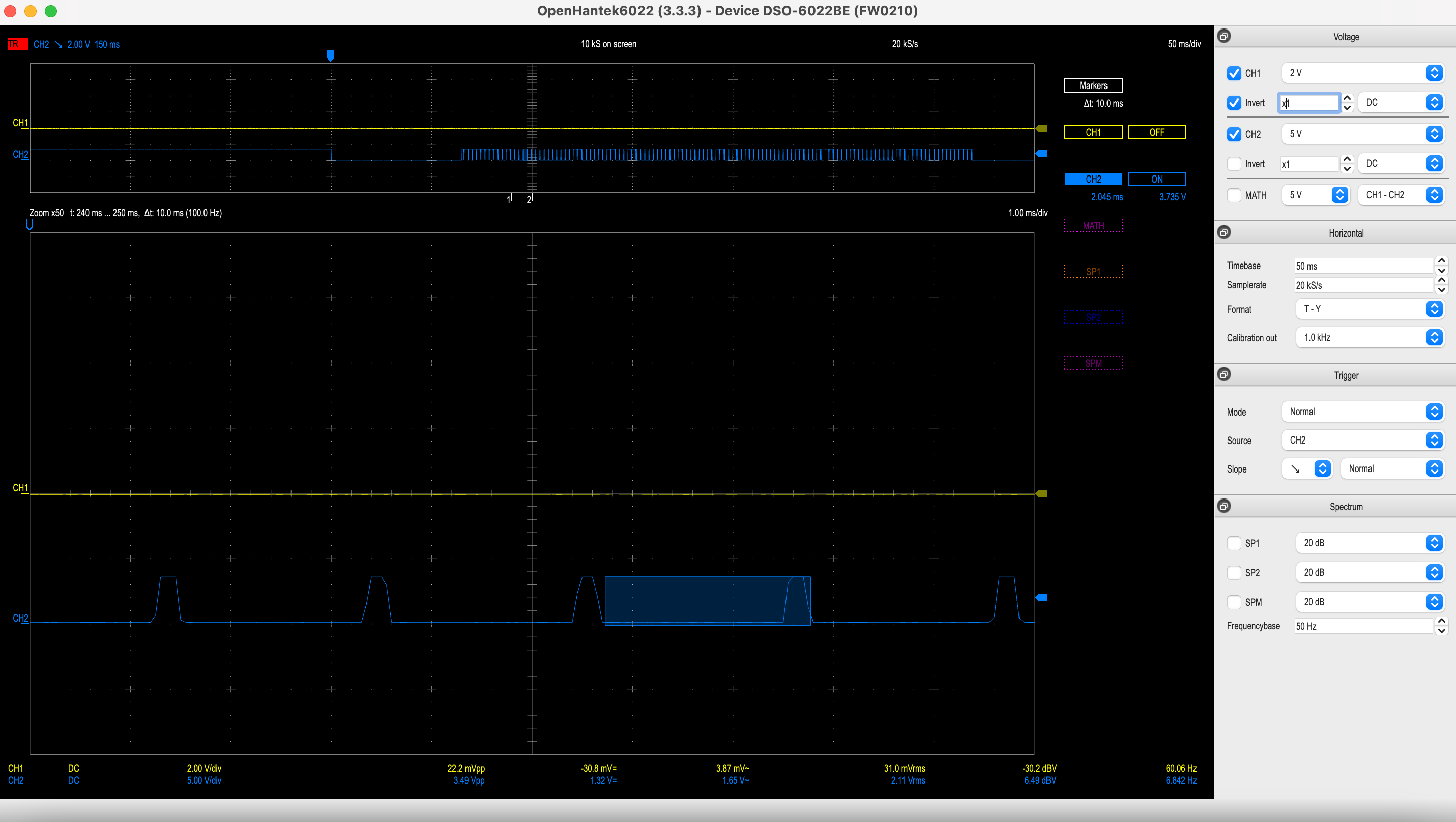
(Note: rise/fall times are really faster; the gentle slope is just an artifact resulting from slowing the sample rate to get enough samples to get past the long opening pulses.)
1 Like
I should be able to test it in a couple of weeks on a real environment and will let you know how it goes
Javier,
Good News!
Finally had a few post-Christmas moments while the family was still sleeping and I hooked up the ESP to an X-Core 400.
I modified the yaml to have only 3 zones and programs, but I can start and stop each zone, and run programs 1-3 just fine.
I connected the ESP8266 through an opto isolator. (I intend to power the device using the 24VAC supply and don’t want any ground problems.)
You can catch a home video where I’m starting different zones on my test setup at youtube.com
Next, I’m going to add the interfaces and hardware to monitor the actual zones (whether started from your code, the physical panel or a program.
I’ve also found that if you do not short out the rain sensor terminals, you can suppress any running program. So I’ve added an option to stop watering.
Congratulations Javier and Thanks for this component.
2 Likes