Kogan Smart Kettle

(Sorry, being a new user, I am limited in how many links and images I can post at once. Forgive me…)

Lovelace

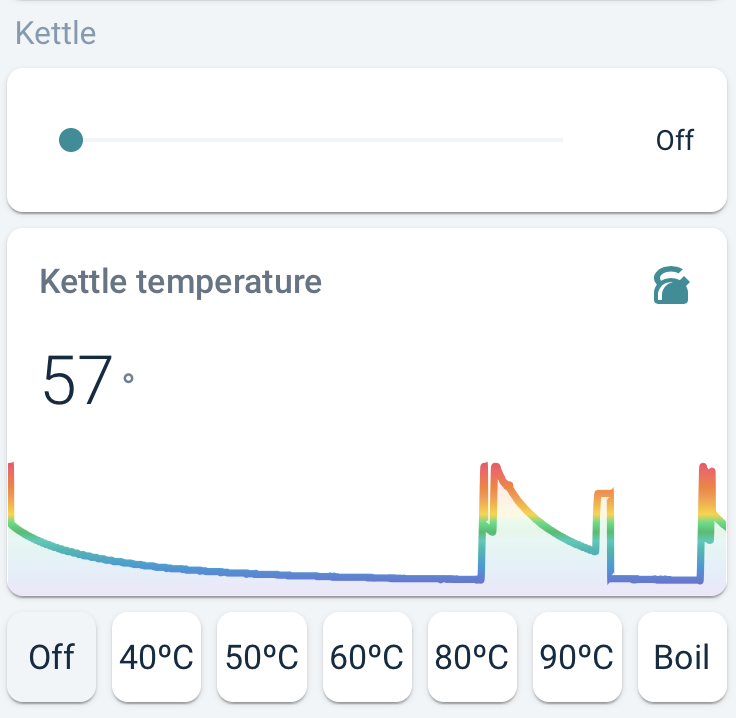
I’m experimenting with a couple of different ways to control the kettle’s input_select in the UI. Thomas Loven’s slider-entity-row provides a slider element: that’s pretty cool, and easy to use:

type: entities
entities:
  - entity: input_select.kettle_mode
    type: 'custom:slider-entity-row'
    full_row: true

I’ve also realized that using RomRider’s Button Card, I can achieve the radio button array that I’ve been seeking for a few purposes for a while now. There are more lines of code there than I might like, because basically you have to set tapping the button to call the input_select.select_option service, while you style the button according to what the input_select’s current option is. And you then repeat this for each of the seven buttons… Here are the first two: the rest are just the same, mutatis mutandis:

type: horizontal-stack
cards:
  - type: 'custom:button-card'
    entity: input_select.kettle_mode
    show_icon: false
    show_state: false
    show_label: false
    aspect_ratio: 1/1
    name: 'Off'
    show_name: true
    tap_action:
      action: call-service
      service: input_select.select_option
      service_data:
        entity_id: input_select.kettle_mode
        option: 'Off'
    state:
      - operator: template
        value: |
          [[[ return states['input_select.kettle_mode'].state === 'Off' ]]]
        styles:
          card:
            - background-color: var(--secondary-background-color)
  - type: 'custom:button-card'
    entity: input_select.kettle_mode
    show_icon: false
    aspect_ratio: 1/1
    name: 40ºC
    show_name: true
    show_state: false
    tap_action:
      action: call-service
      service: input_select.select_option
      service_data:
        entity_id: input_select.kettle_mode
        option: 40ºC
    state:
      - operator: template
        value: |
          [[[ return states['input_select.kettle_mode'].state === '40ºC' ]]]
        styles:
          card:
            - background-color: var(--secondary-background-color)

And of course kalkih’s near-ubiquitous mini-graph-card makes for a pretty representation of the kettle’s temperature over time!

I hope that all this helps someone out there! The best thing? Asking Siri to turn the kettle on via CarPlay while driving home!

6 Likes

Thanks for the detailed post!
It really helped me flash my kettle.

I did not find the RST to ground the MCU so I unsoldered the MCU board from the ESP8266 board.

Also, the base of my kettle did not come off easily, even after I removed the three screws underneath. I found that I did not need to remove that anyway.

Hope this helps someone!

Does anyone know how to open it?

I’ve removed the 3 screws at the base but then nothing seems to budge…

Tom states: 1. Extract the computer board (unscrew base, remove handle cover, remove the computer board from the handle). Which implies needing to remove the base?

while @alistercole says " I found that I did not need to remove that anyway."

so im confused!

Do i need to remove the base?
How is the easiest way to get the handle off?

Thanks!

Guy,

You don’t need to remove the screws on the base of the unit.

Rather you need to carefully pry open the cover on the handle. Start at the bottom. There is a plastic clip that should open with a little pressure from a flat screwdriver or the like.

Cheers

1 Like

Great, thanks for the tip @alistercole!

Just bought a Kogan kettle for $30, but found that Tuya-Convert is not working on my particular model. I’m confident it’s because of the updated firmware being shipped with the unit.

Instead of busting the thing open and soldering/flashing, I settled with pairing it to the TuyaSmart app, and then using the LocalTuya integration from HACS. This gives me a switch, as well as a temperature sensor (DPS 1 and 5 respectively).

image

So far, haven’t found a way to reflect the kettle’s state in HA from manually turning it on, but I don’t think that’s entirely useful right now, anyway.

Hope this helps anyone who’s recently purchased the kettle. If you’ve got any questions on how to get the localkey etc, let me know.

2 Likes

Hey that’s a cool idea, probably going to be enough for some peoples requirements of just turning it on locally. :+1:

Yep!

Also can build your own keep warm/temperature limiting function, since the temperature is exposed and is pretty much update in real-time.

Thanks tbut,

This is my first attempt of low level electrical tinkering. I’ve soldered all the connections per Step #2, but I’m confused at the following steps.

Do I need to connect GPIO-O to the USB-Serial GND and the ESP GND to the ESP VDD?

Is there a specific sequence I need to perform these connections, i.e. connect GPIO-0 to serial GND, then disconnect after boot (to prepare for flash)?

Following step 5, will the device be able to power up and produce an SSID without reconnecting it back to the kettle power source?

Which tools do you recommend to do the flash? I was looking at Tazmotizer.

Apologies for all the questions, total noob here. Here’s my setup so far.

Do I need to connect GPIO-O to the USB-Serial GND and the ESP GND to the ESP VDD?

GPIO 0 needs to be connected to GND (before VCC is connected) so ESP8266 goes into flash mode, and GPIO0 can be connected to GND during the entire flashing process. As for the other MCU, I’m not sure, @tbut7633 did say the other board was overheating and I don’t want to risk it. I desolder the 4 points between the two boards and separate the WiFi board (ESP8266) from the other MCU. This makes things simpler, you don’t need to worry about shutting it off.

Following step 5, will the device be able to power up and produce an SSID without reconnecting it back to the kettle power source?

After flashing, disconnect GPIO0 from GND, then disconnect and reconnect VCC. It should boot into your custom firmware (I use Tasmota) and you can configure it over wifi.

Which tools do you recommend to do the flash? I was looking at Tazmotizer.

I use esptool. Tazmotizer is a good choice too, it uses esptool under the hood.

2 Likes

Hey I have a similar setup now, sometimes updating the dropdown will send another dropdown update command for me. not sure if it will be a problem for u but it has created some trouble for my setup. to get around that, I check the user that triggers dropdown change, if it was created by the nodered user, I’ll just drop the payload.

I have noticed the double change also from time to time.
Bit off topic but its far more noticeable on my Tuya MCU Anko fan from Kmart as it beeps on every change.
I noticed If I change the settings on the device itself that when the UI list updates to reflect the state change that home assistant/node red then sends that out as a command due to the list updating.

There must be a way to check in node red the incoming status update and then block the outgoing list change but its a little over my head at this point in time.

Thanks Aaron. I’ve de-soldered the boards. Last confirmation before I attempt.

Should the TYWE3S have both GND and GPI0-0 connected to the GND of the serial flasher? If so I’ll just solder the 3 together.

I haven’t seen any mention of connecting VCC. Is that the connection labelled 3.3v here https://user-images.githubusercontent.com/3240875/43324672-578ffcbc-917a-11e8-800c-f1d008ca3cf4.JPG

If so, do I just connect that to the 3.3v connection on the flasher?

Yes, VCC is 3.3v. make sure your board is outputting 3.3v (I fried an ESP8266 with 5v before).

Should the TYWE3S have both GND and GPI0-0 connected to the GND of the serial flasher? If so I’ll just solder the 3 together.

That’s fine, but remember, you need to disconnect gpio 0 from GND after flashing (and reboot by disconnecting power and reconnecting) to configure tasmota over wifi.

When the cyclic update happens from NodeRed -> Home assistant, the user ID is attached in the message. you can do this to ignore the state change triggered by nodered in nodered.

msg.data.event.new_state.context.user_id will give u the user id that triggers the state change,
you just need to make sure it’s != your node red’s user id. which can be found in /config/users

So my laptop is picking up the ESP, but it’s failing to read and write from/to the flash. Any ideas?

I have soldered the connections per the sample above.

ESP/SERIAL
RX -> TX
TX > RX
GPI0 > GND
GND - > GND
(the above two are spliced into one dodgy wire connecting to the flasher GND)
VCC -> 3.3V

Could my solder connections just be bad?

nub@laptop:~$ esptool.py --port /dev/ttyUSB0 write_flash -fs 1MB -fm dout 0x0 ./Downloads/tasmota.bin
esptool.py v3.0
Serial port /dev/ttyUSB0
Connecting....
Detecting chip type... ESP8266
Chip is ESP8266EX
Features: WiFi
Crystal is 26MHz
MAC: ec:fa:bc:7a:c5:7b
Uploading stub...
Running stub...
Stub running...
Configuring flash size...
Compressed 601072 bytes to 429021...
Wrote 601072 bytes (429021 compressed) at 0x00000000 in 37.7 seconds (effective 127.6 kbit/s)...
Traceback (most recent call last):
  File "/home/nub/.local/bin/esptool.py", line 386, in command
    p = self.read()
  File "/home/nub/.local/bin/esptool.py", line 331, in read
    return next(self._slip_reader)
  File "/home/nub/.local/bin/esptool.py", line 2632, in slip_reader
    read_bytes = port.read(1 if waiting == 0 else waiting)
  File "/home/nub/.local/lib/python3.8/site-packages/serial/serialposix.py", line 595, in read
    raise SerialException(
serial.serialutil.SerialException: device reports readiness to read but returned no data (device disconnected or multiple access on port?)

During handling of the above exception, another exception occurred:

Traceback (most recent call last):
  File "/home/nub/.local/lib/python3.8/site-packages/serial/serialposix.py", line 398, in _reconfigure_port
    orig_attr = termios.tcgetattr(self.fd)
termios.error: (5, 'Input/output error')

During handling of the above exception, another exception occurred:

Traceback (most recent call last):
  File "/home/nub/.local/bin/esptool.py", line 3969, in <module>
    _main()
  File "/home/nub/.local/bin/esptool.py", line 3962, in _main
    main()
  File "/home/nub/.local/bin/esptool.py", line 3604, in main
    operation_func(esp, args)
  File "/home/nub/.local/bin/esptool.py", line 3011, in write_flash
    res = esp.flash_md5sum(address, uncsize)
  File "/home/nub/.local/bin/esptool.py", line 113, in inner
    return func(*args, **kwargs)
  File "/home/nub/.local/bin/esptool.py", line 780, in flash_md5sum
    res = self.check_command('calculate md5sum', self.ESP_SPI_FLASH_MD5, struct.pack('<IIII', addr, size, 0, 0),
  File "/home/nub/.local/bin/esptool.py", line 413, in check_command
    val, data = self.command(op, data, chk, timeout=timeout)
  File "/home/nub/.local/bin/esptool.py", line 402, in command
    self._port.timeout = saved_timeout
  File "/home/nub/.local/lib/python3.8/site-packages/serial/serialutil.py", line 372, in timeout
    self._reconfigure_port()
  File "/home/nub/.local/lib/python3.8/site-packages/serial/serialposix.py", line 401, in _reconfigure_port
    raise SerialException("Could not configure port: {}".format(msg))
serial.serialutil.SerialException: Could not configure port: (5, 'Input/output error')

Thanks, this is now working as expected

Problem: Tried another USB port and the flash actually transmits/progresses but then fails with an MD5 mismatch.

Resolution: Solved, had to jumper the 5V and VCC connection on the CH340G for a stable 3.3v connection.

nub@laptop:/dev$ tasmotizer.py 
qt.qpa.xcb: QXcbConnection: XCB error: 3 (BadWindow), sequence: 2061, resource id: 33554764, major code: 40 (TranslateCoords), minor code: 0
esptool.py v2.8
Serial port /dev/ttyUSB0
qt.qpa.xcb: QXcbConnection: XCB error: 3 (BadWindow), sequence: 2386, resource id: 33554772, major code: 40 (TranslateCoords), minor code: 0
esptool.py v2.8
Serial port /dev/ttyUSB0
Connecting....
Chip is ESP8266EX
Features: WiFi
Crystal is 26MHz
Uploading stub...
Running stub...
Stub running...
Configuring flash size...
Auto-detected Flash size: 2MB
Erasing flash (this may take a while)...
Chip erase completed successfully in 0.0s
Flash params set to 0x0330
Compressed 388096 bytes to 277941...
Wrote 388096 bytes (277941 compressed) at 0x00000000 in 24.5 seconds (effective 126.8 kbit/s)...
File  md5: c102746728349fca903c0f004f67069e
Flash md5: e2ad804368743876107b60c8672cda29
MD5 of 0xFF is dcdfaee51e7a1597d1a0c4a738bd509f
qt.qpa.xcb: QXcbConnection: XCB error: 3 (BadWindow), sequence: 4621, resource id: 33554799, major code: 40 (TranslateCoords), minor code: 0

Ok managed to successfully flash the ESP, the hash is now matching. It turns out I had to ‘jumper’ the 5v and VCC connections on the CH340G for the 3v3 connection to work. Hopefully I haven’t fried anything.

However there’s now no WiFI when I power the ESP up, I’ve removed the GND and GPIO-0 connections. Do I need to re-attach the other board for WiFI to work, or is the ESP fried?

More than fair chance it is fried. All of the guides I’ve used are very clear about ensuring only 3.3V is used.