@Ben0it Did you find something to control these lights ? 
Thanks !
@Ben0it Did you find something to control these lights ?
Thanks !
Any solutions yet? I’m thinking of buying these led panels, but not sure if they don’t work with home assistant
Hello, sorry for the long inactivity.
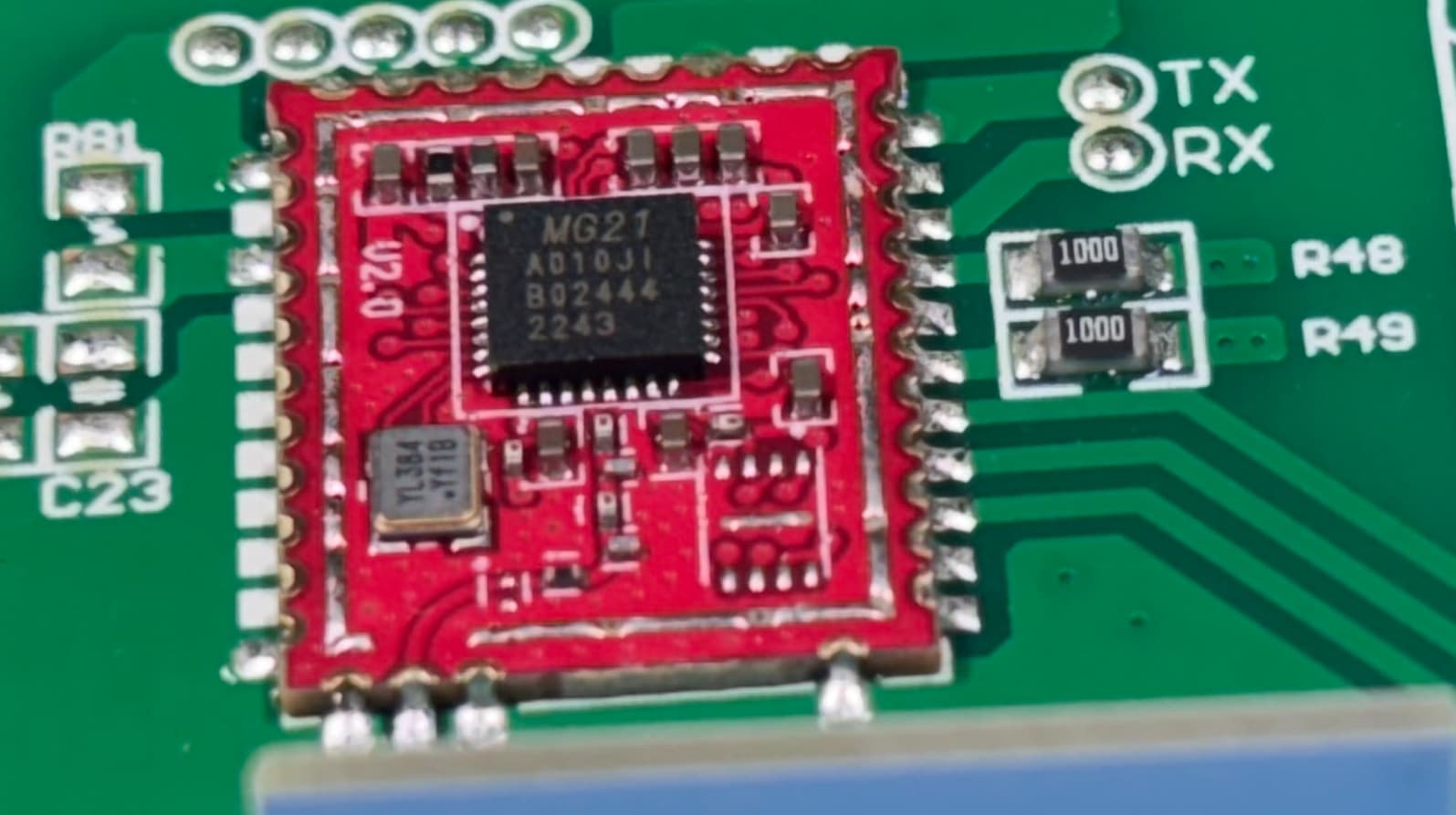
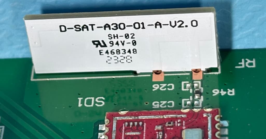
I am now trying to attack the problem on the receiver side, so tonight I have open the panel electronic box :
There seems to be a small PCB for the receiver / controler part :
White insulated electrical wire : might be the antenna.
I suspect the PWM signals control the LEDs : 0% = light off, 100% = full luminosity.
After seeing this, I now have the strong desire to try to replace this small PCB by an ESP32 running with ESPHome ![]()
I will keep you informed about my findings.
Confirmed : I have un-soldered the small PCB from the rest of the main board and powered it with 3.3V :
Oscilloscope setup :
PWM signal frequency is 15.5 kHz.
When light is turned off with remote, both PWM channels are at 0V.
Here are different setups configured with original remote control with the screenshot of the signals displayed by the oscilloscope:
Full cold :

Half cold/warm :

Full warm :

Full cold :

Half cold/warm :

Full warm :

Next step : recreate signals with an ESP32 (or ESP8266) to drive the LEDs.
Possible ESPHome components :
Made some progress this morning, I connected an ESP32 D1 in place of the original PCB :
Powered the lamp on…ESP keeps on rebooting. I believe it draws too much power from the supply sized for the original PCB.
I tried with an external source and it works fine. Using the following setup in ESPHome device:
output:
  - platform: ledc
    pin: GPIO21
    id: output_cold
    frequency: 15500

  - platform: ledc
    pin: GPIO22
    id: output_warm
    frequency: 15500

light:
  - platform: cwww
    name: "Lumière établi"
    cold_white: output_cold
    warm_white: output_warm
    cold_white_color_temperature: 6536 K
    warm_white_color_temperature: 2000 K
    constant_brightness: true
    restore_mode: RESTORE_DEFAULT_OFF
I will have to find a suitable power source from the main PCB. Edit : After testing around, I have found no easy source to tap ![]()
A dedicated power supply would be needed (for the test I tried with a single Li-Ion cell, directly soldered to ESP32). Maybe a power supply module like this one could do the trick : Hi-Link HLK-PM03.
Be careful when hooking or playing with things on mains voltage.
Control component in Home Assistant :
Nice catch ! do you think a capacitor between 3.3v and GND can do to trick to avoid esp32 reboot ?
@Ben0it I don’t know if you have these in stock, but it seems esp8266 (ESP12) consume less power than ESP32 (basic one).
I have read that ESP32-C3 seems to best choice for power consumption, do you think it can work without external power ?
Or maybe Zigbee, CC2530 https://fr.aliexpress.com/item/1005003103244824.html
with this firmware LED edition firmware – Zigbee Hobbyist. Rock Pi 4 SBC
Yes, I tried with 10 µF, 470 µF and 4700 µF chemical capacitors in parallel to the power supply of the ESP32.
I even inserted a diode (1N4001) in series to prevent current from flowing back from ESP to main PCB : same result, power supply drops down too much a couple of ms and comes back, thus resetting the ESP32 every second or so.
Thanks for the hints, I do have some spare ESP8266 in stock, I will try this weekend with these.
Thanks for the pointers, the Zigbee modules seems interesting, I will search information about them.
An alternative I have been searching too was a complete CWW module, but I didn’t find something powerful enough and/or powered with mains (240 VAC), This kind of module. They tend to be rather expensive too.
Hello,
I also bought such a module (it was 50€ for the 120x30). I thought it was IR since the remote has a nice LED that is not visible when clicking, but well, I was wrong. Thanks @Benoit for all your reverse engineering!
When dismantling the RF module, did you have to unsolder it? I’m not sure whether it’s just a connector, or if it’s soldered.
For reference, Integrating LED light that comes with generic with 2.4GHz RF remote/controller - #10 by thezfunk seem to be using the same controller as us
I’m not sure which go I’ll way. The EspHome is one way, but the power issue is pretty annoying. I’m more a software guy, so I might try the software way, but I’m not sure what kind of low-power 2.4G emitter I could use…
Would you be able to know how much power you can get out of that 3.3V rail to better target what device to use?
Thanks for all your work
Judging by the YouTube channel of colasmart, which seems like the “true” manufacturer of the remote, the remote is at least 7 years old

I have not managed to replicate this, I’ve only seen the signal at 2406.5675Mhz-2407.5313Mhz
I have managed to replay the signal for the lamp, I used the one at ~2406.5675Mhz. I’ll try to demodulate it and reverse engineer the protocol.
@fuomag9 Did you managed to get something working ?
Unfortunately I have not had much time to look into it and I’m stuck at replay attacks for now ![]()
There seems to be a Zigbee+Bluetooth version of the Inspire Gdansk LED panel (site in French).
Maybe I’ll try to get one, to study its LED controller and see if a retrofit would be possible ![]()
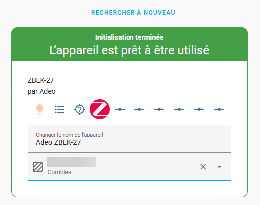
Got one, couldn’t resist ![]()
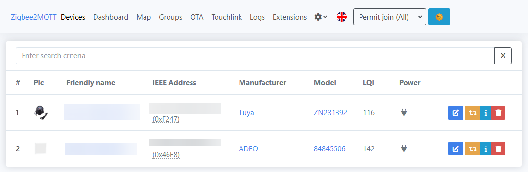
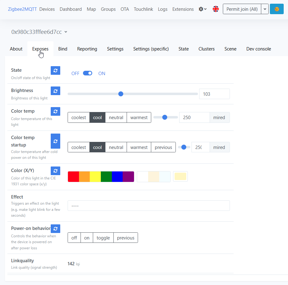
So far it works out of the box with Zigbee2MQTT :
I will try with ZHA later on and report here.
Edit: from ZHA :
device is not behaving correctly natively with ZHA. An adaptation (quirk ?) seems needed.
Hello, thanks for the test !
do you think we can get the adeo zigbee controller to put on the old one ?
Do you have the controller reference ?
Just wanted to thank everyone for all the valuable information shared in this thread. It made it possible for me to convert my Leroy Merlin INSPIRE EMINGO ceiling lamp from its original RF controller to an ESP32 running ESPHome (using either Thread or Wi-Fi).
I’ve documented the full process here, in case it’s useful to anyone: