Huge thanks again to everyone doing the heavy lifting on the XYE interface. I have a bit of a breakthrough on the concealed-duct unit I described in post #97, and I wanted to put the full result back here instead of just saying “it works.”
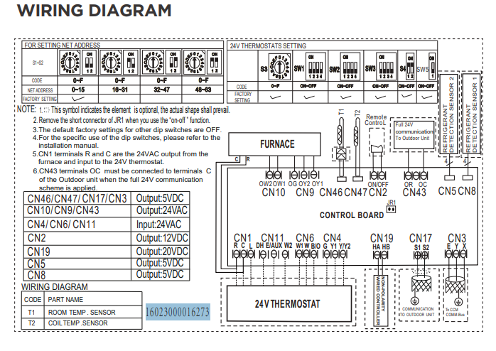
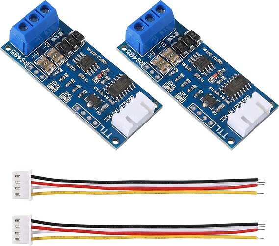
For context, this is an ACiQ/Midea 24K concealed-duct AHU on a 6-zone condenser. I have an M5Stack Atom + Tail485 on XYE at 4800 baud, while the KJR-120N wired controller is still attached on its separate controller bus.
What I’ve proved
- The head reports capabilities
0x14, so it does not advertise the EXTERNAL_TEMP capability (0x80).
- The ESPHome component sends the C6 Follow-Me frame successfully, but this particular head ignores it.
- I heated the wired thermostat with a heat gun. Its reported temperature climbed to about 89°F while the independent living-room sensor stayed around 72°F, and the unit continued regulating against the wired thermostat temperature.
- Setpoint writes sent over XYE are accepted, echoed back, and remain authoritative even with the wired controller attached.
So native C6 Follow-Me is a dead end on this head, but XYE setpoint control gives us another path.
The fallback that is working
Every 60 seconds the ESP32 calculates:
head setpoint = desired room target + (wired thermostat temperature - independent room temperature)
Example: if I want the room at 70°F, the wall controller sees 73°F, and the room sensor sees 71°F, the ESP32 sends a 72°F setpoint to the head. As those two measured temperatures converge, the bias disappears.
The loop is on the ESP32, so it does not depend on a Home Assistant automation continuing to run. It exits when the climate is off, skips invalid sensor values, clamps the command to 65–78°F, and has a switch that disables room tracking immediately. A live result looked like this:
target=70.0F wall=22.8C room=22.4C -> setpoint=70.7F
The unit echoed the setpoint and held it. The independent room sensor was also within about 0.4°F of a separate handheld reading.
I am not claiming the underlying offset math is new control theory. What may be useful/novel here is applying a continuously recalculated two-sensor bias on-device as a software Follow-Me fallback for an XYE head that transmits and receives normally but ignores C6. I found the static-offset discussion in #38, the fake Follow-Me idea in #140 and #147, and manual setpoint-offset tuning in #150, but I did not find this exact fallback. If somebody already published it, please point me there.
Important caveats
- This is validated on one ACiQ concealed-duct head, primarily in cooling. Different unit families and controller-bus topologies may behave differently.
- I still want to add a minimum-change threshold and an explicit stale-room-sensor timeout before calling the loop finished.
- The working component is currently a local vendor:
larsonm-personal@62a3047 for the raw-Fahrenheit/C0 behavior, plus the WAIT_DATA recovery from HomeOps PR #136. The raw-Fahrenheit/C0 work is still represented publicly by HomeOps PR #137, so the upstream pieces are split at the moment.
- The YAML below therefore references a local
components/midea_xye directory; it is the complete configuration I am running, but that local component directory is also required to compile it.
If anyone has a head without EXTERNAL_TEMP, or sees valid C6 frames being sent but ignored, I would really like another data point.
Full working ESPHome configuration
substitutions:
  name: livingroom-hvac
  friendly_name: "Living Room HVAC"
  comment: "ESPHome flashed M5Stack Atom with Tail485 attached to livingroom/kitchen AHU in attic"

esphome:
  name: ${name}
  name_add_mac_suffix: false
  friendly_name: ${friendly_name}
  comment: ${comment}

esp32:
  board: esp32dev
  framework:
    type: arduino

# Enable logging (but not via UART)
logger:
  #baud_rate: 0
  #logs:
  #  component: ERROR

# Enable Home Assistant API
api:
  encryption:
    key: !secret api_key
#  services:
#    - service: follow_me
#      variables:
#        temperature: float
#      then:
#        midea_ac.follow_me:
#          temperature: !lambda "return temperature;"
#          beeper: false

# Enable wifi
wifi:
  ssid: !secret wifi_ssid
  password: !secret wifi_password
  use_address: 192.168.1.236

# url: https://github.com/exciton/esphome
external_components:
  # #942 (2026-07-11): switched from the pinned git source to a LOCAL vendored
  # copy of the larsonm-personal @62a3047 (ch_concealed) midea_xye component so
  # we could patch the WAIT_DATA deadlock. That build has the correct C&H/ACiQ
  # raw-Fahrenheit decode (temperature_encoding: RAW + target_temperature_source:
  # C0; wire-proven 0x46=70degF) but NO recovery from a missed/short/over-long
  # reply — one glitched response permanently strands the poll loop (all bus
  # telemetry silently freezes; current_temperature/target go null while the ESP
  # stays healthy). This regressed the bring-up ~2 days after it went live.
  # The vendored copy under components/midea_xye/ backports HomeOps upstream
  # main's recovery path into climate_midea_xye.cpp's no-reply branch (see the
  # #942 comment there). Everything else is byte-identical to @62a3047.
  #
  # History: mdrobnak@delays_updated (original deadlock, dead 100ms timeout) ->
  # larsonm-personal @62a3047 (raw-degF decode, deadlock still present) ->
  # this local vendored + patched copy (raw-degF decode + deadlock recovery).
  #
  # UPSTREAM EXIT: when the raw-Fahrenheit decode (temperature_encoding: RAW /
  # target_temperature_source: C0) lands in a HomeOps release that ALSO carries
  # the recovery path, delete homeassistant/esphome/components/midea_xye/ and
  # repoint this block to that release tag.
  - source:
      type: local
      path: components
    components: [midea_xye]

#i2c settings for dfrobot MiCS-4514 gas sensor
i2c:
  sda: GPIO25
  scl: GPIO21
  scan: true
  id: bus_a

# UART settings for RS485 converter dongle (required)
uart:
  tx_pin: GPIO26
  rx_pin: GPIO32
  baud_rate: 4800
  rx_buffer_size: 1024
  # #942 diagnostics: log both directions, chunked at the XYE prologue 0x55.
  # Capture C0-RX byte 10 (setpoint) + 11 (T1) vs known values to settle the
  # raw-Fahrenheit variant (PROTOCOL.md Temperature Encoding; HomeOps#137).
  debug:
    direction: BOTH
    after:
      delimiter: [0x55]
#  debug: #If you want to help reverse engineer
#    direction: BOTH
    #dummy_receiver: true
    #after:
    #  delimiter: [0x55]

# Enable esphome OTA updates
ota:
  password: !secret ota_password
  id: my_ota
  platform: esphome

# Main settings
climate:
  - platform: midea_xye
    name: Living Room HVAC
    id: midea_ac
    period: 1s                  # Optional. Defaults to 1s
    timeout: 300ms              # #942: honored on HomeOps; generous vs ~67ms frame time
    beeper: false               # Optional. Beep on commands.
    #default_target_temperature_low: 18°C
    #default_target_temperature_high: 24°C
    #custom_auto: true
    use_fahrenheit: true
    temperature_encoding: RAW       # #942: unit sends raw degF bytes (wire-proven)
    target_temperature_source: C0   # #942: unit lacks C4 (all-0xFF sentinel)
    compressor_aware_action: true   # #942 batch: hvac_action reflects real compressor state
    sync_fan_mode_from_device: true # #942 batch: head-unit fan changes reflect into HA
    # #1021: native XYE follow-me is INERT on this head — the heat-gun test proved
    #   it regulates to the WALL THERMOSTAT (internal_current_temperature) and
    #   ignores external follow-me (capability 0x14, no EXTERNAL_TEMP). Room-based
    #   control is done on-device via the SETPOINT-BIAS loop (see the number:/
    #   switch:/interval: blocks below), so the follow_me_sensor binding is removed.
    visual:                     # Optional. Example of visual settings override.
      min_temperature: 65 °F    # min: 17
      max_temperature: 78 °F    # max: 30
      temperature_step: 0.5 °F  # min: 0.5
#    visual:                     # Optional. Example of visual settings override.
#      min_temperature: 17 °C    # min: 17
#      max_temperature: 30 °C    # max: 30
#      temperature_step: 0.5 °C  # min: 0.5
    supported_modes:            # Optional.
      - FAN_ONLY
      - HEAT_COOL
      - COOL
      - HEAT
      - DRY
    supported_presets:      # Optional
      - BOOST
    # outdoor_temperature: DISABLED (#942 cleanup) — this AHU never populates
    # the field (C4 response is all-0xFF sentinel; the value rendered as
    # -4degF pre-RAW and ~0degF post-RAW, both meaningless). Re-enable only
    # if the unit ever gains an ODU on the bus.
    temperature_2a:             # Optional. Inside coil temperature
      name: Inside Coil Inlet Temp
    temperature_3:
      name: Outside Coil Temperature
    timer_start:                # Optional. On timer duration
      name: Timer Start
    timer_stop:                 # Optional. Off timer duration
      name: Timer Stop
    error_flags:                # Optional.
      name: Error Flags
    protect_flags:              # Optional.
      name: Protect Flags
    static_pressure:
      name: Static Pressure
      min_value: 0
    # #942 batch (2026-07-09): duty/diagnostic surface
    fan_speed:
      name: Fan Speed
    internal_current_temperature:   # = the WALL THERMOSTAT reading the head
      name: Internal Current Temperature   # regulates to (heat-gun-proven, #1021);
      id: head_wall_temp                    # °C internally (HA shows °F). Bias ref.
    internal_target_temperature:
      name: Internal Target Temperature
    defrost:
      name: Defrost
    compressor_active:              # the duty-cycle signal (A/B-correlation class)
      name: Compressor Active

button:
  # #942: manual unwedge affordance (and future automation hook if the
  # component ever freezes again — restart clears any wedged state).
  - platform: restart
    name: Living Room HVAC Restart

number:
  # #1021 setpoint-bias: the DESIRED ROOM temperature (°F). HA / your schedules
  # set this one value; the interval loop below drives the head's setpoint so the
  # ROOM converges here. Plain number (no device_class) so HA does not unit-convert
  # it — the value is °F as typed and the loop converts to °C.
  - platform: template
    name: "Living Room Room Target"
    id: room_target
    unit_of_measurement: "°F"
    min_value: 65
    max_value: 78
    step: 0.5
    initial_value: 72
    restore_value: true
    optimistic: true
    mode: box

switch:
  # #1021 setpoint-bias: room-tracking on/off. OFF = climate behaves normally
  # (setpoint is whatever you/the wall set). ON = the interval loop overrides the
  # head's setpoint every 60s to track Room Target. Default OFF until validated.
  - platform: template
    name: "Living Room Room Tracking"
    id: room_tracking
    optimistic: true
    restore_mode: RESTORE_DEFAULT_OFF

interval:
  # #1021 setpoint-bias loop. Every 60s, when Room Tracking is ON and the head is
  # not OFF:  head_setpoint = Room Target + (wall_thermostat − room_sensor)
  # so the head cools/heats until ITS reference (the wall thermostat) hits the
  # biased target, at which point the ROOM reads Room Target. wall_thermostat =
  # internal_current_temperature (heat-gun-proven; °C in ESPHome). All math in °C;
  # set_target_temperature() takes °C. FAIL-SAFE: skip if any input is NaN (e.g.
  # the room sensor went stale) — the head just holds its last setpoint. Clamp to
  # the head's safe range (65–78 °F).
  - interval: 60s
    then:
      - lambda: |-
          if (!id(room_tracking).state) return;
          if (id(midea_ac).mode == climate::CLIMATE_MODE_OFF) return;
          float wall_c = id(head_wall_temp).state;                     // wall thermostat (°C)
          float room_c = id(room_temp_c).state;                        // room sensor (°C)
          float tgt_c  = (id(room_target).state - 32.0f) * (5.0f/9.0f);// desired room °F→°C
          if (isnan(wall_c) || isnan(room_c) || isnan(tgt_c)) return;  // fail-safe
          float sp_c = tgt_c + (wall_c - room_c);                      // biased setpoint (°C)
          const float lo = (65.0f - 32.0f) * (5.0f/9.0f);              // 65 °F
          const float hi = (78.0f - 32.0f) * (5.0f/9.0f);              // 78 °F
          if (sp_c < lo) sp_c = lo;
          if (sp_c > hi) sp_c = hi;
          auto call = id(midea_ac).make_call();
          call.set_target_temperature(sp_c);
          call.perform();
          ESP_LOGI("setpoint_bias", "target=%.1fF wall=%.1fC room=%.1fC -> setpoint=%.1fC (%.1fF)",
                   id(room_target).state, wall_c, room_c, sp_c, sp_c * 9.0f/5.0f + 32.0f);

sensor:
  # #1021 setpoint-bias: the operator-installed room sensor, imported from HA
  # (°F) and converted to °C — the "room" term of the on-device bias loop.
  # internal:true — it's a loop input, not a new HA entity (the original HA
  # sensor sensor.living_room_temperature_temperature stays the display).
  - platform: homeassistant
    entity_id: sensor.living_room_temperature_temperature
    id: room_temp_c
    internal: true
    filters:
      - throttle: 15s
      - heartbeat: 60s
      - debounce: 2s
      - lambda: return (x - 32.0) * (5.0/9.0);   # °F → °C (ESPHome climate is °C)
  - platform: wifi_signal
    name: Living Room HVAC Wi-Fi Signal
    update_interval: 60s

  - platform: uptime
    name: "Uptime"
    id: uptime_sec
    internal: true

  - platform: template
    name: Living Room HVAC Uptime Days
    lambda: |-
      return (id(uptime_sec).state/60)/60/24;
    icon: mdi:clock-start
    unit_of_measurement: days
    update_interval: 60s

  - platform: mics_4514
    i2c_id: bus_a
    address: 0x75
    nitrogen_dioxide:
      name: Nitrogen Dioxide
    carbon_monoxide:
      name: Carbon Monoxide
    hydrogen:
      name: Hydrogen
    ethanol:
      name: Ethanol
    methane:
      name: Methane
    ammonia:
      name: Ammonia
    update_interval: 60s