Midea A/C via local XYE

Yeah my unit seems to have 2 separate buses, both electrically RS485:

  • CN9 XYE “to CCM comm. bus”
  • CN40 to “wire controller”, optionally daisy chained via WiFi adaptor

I got some photos of the terminals and the wiring diagram inside the unit, which is the complete version from Midea rather than the “sanitised” version from Actron Air in my case.

I’m guessing that the CN20 link from indoor to outdoor unit is also electrically RS485. Now I am also tempted to sniff this and see if it reveals some interesting data (e.g. outdoor fan speed, compressor speed, EEV opening angle).

Ah hah. Ok.
My RS485 connector I’m using, which you call CN40, is labeled CN14 on my unit. (Name not visible in this pic, but I saw it in another - it’s the one on the bottom right with the red connector)

And here’s my circuit diagram for reference:

So your CN9 would be my CN3. And you’ve tested both sets of wiring and you get different results on the CN9… Interesting.

I’m not sure how mine is, and I’m kinda feeling a bit lazy haha. Whatever the case is, my plan is to keep using the extended functionality - I don’t think C6 will work on your CN9 if C4 errors out, as they seem “releated”

Having the compressor duty cyle or speed would be fine, but I can infer that from the output temps too. Now the unit does a LOT less work than it was before using the 24V setup and it’s just as nice if not nicer in here.

-Matt

I am happy to see you progressing this.

I have a ducted minisplit that is senville branded. I have spent an unbelievable amount of time working on this myself. My home had an addition that was not ducted with the main central heat pump, so we had a mini split installed. The thermostat is on the same wall our fireplace is on, and the addition is all windows, so it gets very cold in the winter towards the back of the addition where we sit. I wanted to do a remote mounted temp sensor (which i use to control our fireplace) to control the minisplit to make everything work in sync and provide interlocks so someone isn’t turning on the main unit heat, and running ac out in the addition.

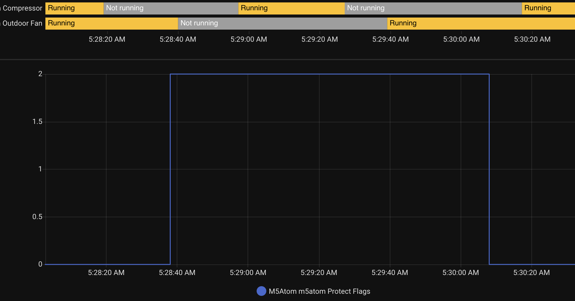
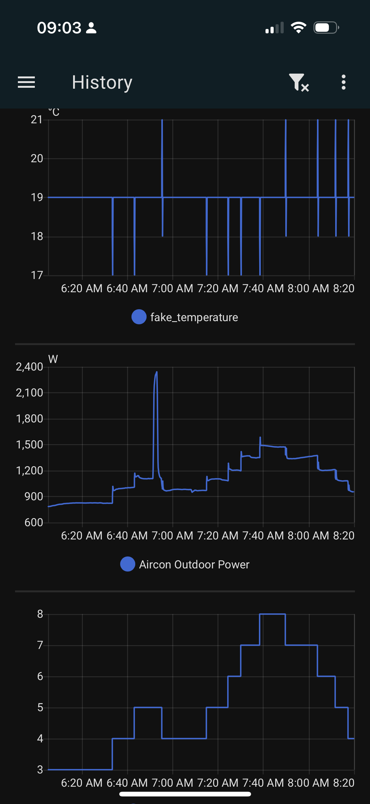
There are a LOT of threads out there about the midea communications. My unit had a wall thermostat that was 5 wire. Most of the threads talk about the 4 wire thermostats. My unit has multiple communication busses. I have tried to switch to the 4 wire thermostat and an esp32 connected to the remote unit in the crawl space that is connected to the older 5 wire thermostat. I removed the Tsop from that board and hard wired the esp32 to send IR follow me commands, then using the uart through a level shifter to set the temp, control on and off, and such, however I don’t fully feel its working properly. The unit never actually shuts the fan down. It does ramp, I do have it regulating temp, but the fan never shuts down when the fan is set to “auto”

Now knowing what I do now and understanding how the follow me commands work, I should have just removed the temp sensor from the internal board, used a digital pot to control the temp remotely. It probably would have been a lot easier.

The issue I have is once I switched to the 4 wire thermostat, it will only display Celsius. I have contacted Senville, they sent me a second thermostat for free saying that it should display Fahrenheit but it doesn’t. I spent a lot of time on the phone with the tech support about it and it was never resolved.

It also seems as though the uart is expecting *C where as the IR commands are sent to the receiver board as *F and displays *F

I have not found a way to do the follow me commands with UART that completely bypasses any IR commands. I can’t use the 5 wire thermostat because it doesn’t update when the esp32 changes the the set temp via uart because it does not have 2 way communication it appears.

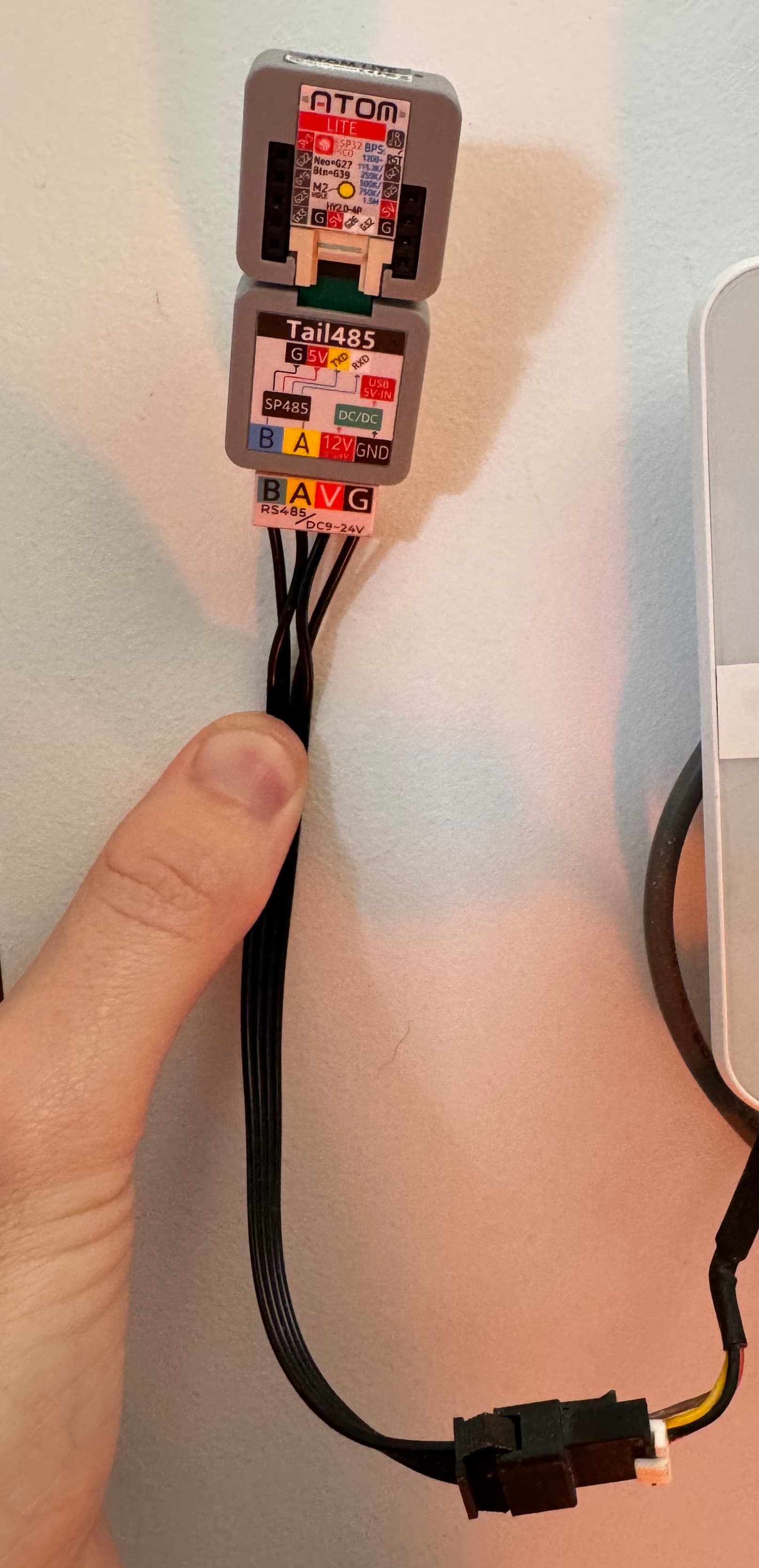
I would like to dig into the rs485 side of things because it seems as though that is the only communication protocol that does everything. I don’t understand the logic of all of these different communications especially when they do not all talk to each other.

My board has RS485 marked on it, and its been a little while but I believe it says xye as well somewhere. I will continue to follow this thread!

It finally got cold enough here to catch a defrost cycle in my logs. Bit 2 of byte 24 (0x18, “field 25”)

05:20:00: <<< AA:C0:00:00:00:00:30:10:84:00:14:XX:XX:XX:XX:00:00:00:00:03:00:00:00:00:00:00:00:00:00:00:XX:55
                :  :  :  :  :  :  :  :  :  :  :  :  :  :  :  :  :  :  :19:  :  :  :  :  :  :  :  :  :  :  :
05:28:19: <<< AA:C0:00:00:00:00:30:10:84:00:14:XX:XX:XX:XX:00:00:00:00:02:00:00:00:00:00:00:00:00:00:00:XX:55
                :  :  :  :  :  :  :  :  :  :  :  :  :  :  :  :  :  :  :  :  :  :  :  :24:  :  :  :  :  :  :
05:28:38: <<< AA:C0:00:00:00:00:30:10:84:00:14:XX:XX:XX:XX:00:00:00:00:02:00:00:00:00:02:00:00:00:00:00:XX:55
                :  :  :  :  :  :  :  :  :  :  :  :  :  :  :  :  :  :  :19:  :  :  :  :  :  :  :  :  :  :  :
05:28:40: <<< AA:C0:00:00:00:00:30:10:84:00:14:XX:XX:XX:XX:00:00:00:00:00:00:00:00:00:02:00:00:00:00:00:XX:55
                :  :  :  :  :  :  :  :  :  :  :  :  :  :  :  :  :  :  :19:  :  :  :  :  :  :  :  :  :  :  :
05:28:57: <<< AA:C0:00:00:00:00:30:10:84:00:14:XX:XX:XX:XX:00:00:00:00:01:00:00:00:00:02:00:00:00:00:00:XX:55
                :  :  :  :  :  :  :  :  :  :  :  :  :  :  :  :  :  :  :19:  :  :  :  :  :  :  :  :  :  :  :
05:29:27: <<< AA:C0:00:00:00:00:30:10:84:00:14:XX:XX:XX:XX:00:00:00:00:00:00:00:00:00:02:00:00:00:00:00:XX:55
                :  :  :  :  :  :  :  :  :  :  :  :  :  :  :  :  :  :  :19:  :  :  :  :  :  :  :  :  :  :  :
05:29:39: <<< AA:C0:00:00:00:00:30:10:84:00:14:XX:XX:XX:XX:00:00:00:00:02:00:00:00:00:02:00:00:00:00:00:XX:55
                :  :  :  :  :  :  :  :  :  :  :  :  :  :  :  :  :  :  :  :  :  :  :  :24:  :  :  :  :  :  :
05:30:08: <<< AA:C0:00:00:00:00:30:10:84:00:14:XX:XX:XX:XX:00:00:00:00:02:00:00:00:00:00:00:00:00:00:00:XX:55
                :  :  :  :  :  :  :  :  :  :  :  :  :  :  :  :  :  :  :19:  :  :  :  :  :  :  :  :  :  :  :
05:30:17: <<< AA:C0:00:00:00:00:30:10:84:00:14:XX:XX:XX:XX:00:00:00:00:03:00:00:00:00:00:00:00:00:00:00:XX:55

And the protect flags already have entities exposed, yay! So in HA this sequence looks like:

Meanwhile, I am having great success modulating the compressor’s speed via C6 feels like messages. This is consistently behaving the same as it was via IR. The new trick I’ve figured out is a simpler and more robust way to increment & decrement the compressor speed via a specific sequence of feels like values in quick succession. My new technique also works in heating mode, which I never got working properly before.

Aside from interacting better with my custom PID thermostat / VAV zone controller, this would enable more precise tracking of surplus solar PV production as it effectively commands a ~200W increase/decrease of power consumption.

For beeper?
beeper=true
Not work

That variable appears to be left over from copy/paste. My system never beeps on control via RS485.

To me this is desirable. I didn’t know how to prevent it from beeping when controlling via IR.

Hi Matt,

I am a bit of a newbie here. While I feel comfortable with all kinds of wiring, and some coding, I get a bit lost with this hardware. I understand that the reference to the hardware you made is the RS485 that connects to the XYE terminals on the AC unit. However, I guess we would also need something to send this through wifi to the Home Assistant machine right? I am quite overwhelmed by the amount of boards available. Any advice?

Thanks in advance, and a lot of kudos, you seem to have already decoded most of the signals.

I suggest M5 Atom Lite with one of their RS485 interface boards, which all include a 4 wire terminal block that easily wires in and powers it from the 12V DC supply to the wall controller. The “Tail485” variant is particularly neat and compact, perfect for this application.

Full bill of materials:

1 Like

Do I need RS485 port on motherboard or I can use XYE terminals? All I found on my HVAC motherboard is XYE along with wifi 4 pin connectors. That’s duct Midea DCTB-48R32IVT unit