With a large battery I suppose…
Agreed but the sensor need power which will drain the battery
ESP32-H2 is so long to come … It’s already a year waiting 
May be check under this Ebyte CC2530 2.4GHz Zigbee SMD Wireless Module (E18-MS1-PCB) Zigbee compatibility
1 Like
All sensors drain battery! hehe. Hence a large battery.
Let’s see 0.1ah for six months is what, >400ah? (don’t trust my math…)
Hey Scottua25,
As mentionned no, currently there isn’t. They do have a Zigbee board in preparation but it’s going to be forever before ESPHome supports it, if it ever does.
If you really want Zigbee you can grab something like a xbee instead, which is kind of a similar thing to an esp32. But sadly there’s not an ESPHome equivalent for it, you’d have to program it yourself.
And for having tried I can tell you the ZCL will not fit on it in micropython mode, so it’ll have to be C if you want it to actually join an existing network. Not an easy project !
You could also look into ESP Now, which is a way to get esp devices to talk to each other directly a bit like Zigbee. Maybe you could use that to relay messages to an esp closer to your wifi access point, if range is the issue. Never tried but my understanding is that there’s a few addons for ESPHome that add support for ESP Now, and it works even when connected to a regular network at the same time.
Zigbee Router (repeater) + mmWave looked like an useful idea. ZigBee does not necessarily run with battery. ZR is typically powered by main power.
I notice quite a bit of switch installation for occupancy sensor (see below). It probably nice to have mmWave sensor with ZR instead of using PIR.

If you install them through out your house, it should help with our other Zigbee devices since it is also an repeater.
@crlogic @phillip1
I noticed some complains from aqara fp1 users detecting ceiling fan movement similar to dfrobot.
Anyway, one of their solution was covering it with some tinfoil. Just wondering if this works for the dfrobot


Haven’t tried foil tape. If orientation didn’t solve it, I’d add a PIR. That’s the great part of being a DIY sensor 
Hello,
I started this project. The sensor works well and I have the same question: is it possible to disable the flashing red led on the DDFRobot SEN0395 sensor? I thought I would find a solution on the YAML side of ESPhome but I couldn’t find anything.
I think that in the long term, this led will be painful! Thank you for your feedback
Soldering iron, nail polish, tape…? 
1 Like
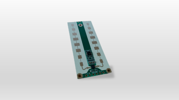
Any readers here have contacts to source the larger brethren of the DFRobot mmWave?
Looks familiar eh…
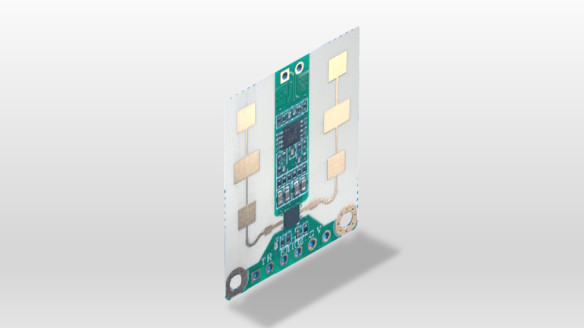
Multi-dimensional array!


More dB I am assuming…
Datasheet
http://www.leapmmw.com/wp-content/uploads/1609/47/用户手册V1.01:HS2xx3A系列人存在检测模块.pdf
I usually just smash the led lol.
I am not to be held accountable for fried chips
Edit: crlogic found a secret way to disable it with code pls don’t smash
1 Like
Anyone tried this chip?
Or
1 Like
The heartbeat module looks very interesting…
Buy it and tell us how it works!
Progress!
More work to do…
- add feedback lambda
- add sensitivity which DFRobot has not documented.
1 Like
How do you do that, setLedMode 1 1 it looks like ?
Correct. Don’t have the lambda ready to keep things in sync quite yet. Here’s a start…
switch:
  - platform: template
    name: "LED"
    id: "led"
    optimistic: true
    restore_state: true
    assumed_state: true
    turn_on_action:
      - uart.write: "sensorStop"
      - delay: 1s
      - uart.write: "setLedMode 1 0"
      - delay: 1s
      - uart.write: "saveCfg 0x45670123 0xCDEF89AB 0x956128C6 0xDF54AC89"
      - delay: 3s
      - uart.write: "sensorStart"
    turn_off_action:
      - uart.write: "sensorStop"
      - delay: 1s
      - uart.write: "setLedMode 1 1"
      - delay: 1s
      - uart.write: "saveCfg 0x45670123 0xCDEF89AB 0x956128C6 0xDF54AC89"
      - delay: 3s
      - uart.write: "sensorStart"
4 Likes
OP has been updated w/ the latest code including new Sensitivity control.
2 Likes
Okay, so that’s some awesome work ! Thank you for sharing !
How did you manage to find these features ? Did you just threw strings at the uart and see what sticked ?
I see that the sensitivity has steps from 1 to 9 and defaults at 7. Have you already played with it ? Did you change the setting of your sensors ?
Any guess as to how the “Target detection” works ?
I see strings like these :
$JYRPO,2,1,2.398, ,4.969, , *\r\n$JYRPO,2,2,3.000, ,9.906, , *\r\n$JYBSS,1, , , *\r\n
It seems like every $JYRPO corresponds to one tracked target. You also still get the usual $JYBSS at the end.
I don’t understand why we would have 4 sets of number per $JYRPO though. The first 2 seem to be simply indicators of the target number or something.
I’ve setup the DFR sensor on Tasmota, I’ll share later on what I’ve learned (spoiler alert : I don’t recommend it.  )
)