MQTT433gateway with a NodeMCU v3 - No data received

I was originally using an Arduino Mega 2560 with RFLink and a connected RXB6 RF Receiver on TX1-19 to listen to a PIR sensor and a door sensor in my house. It worked fine but needed to be plugged into a USB port to work so I wanted to move to something more versatile.

I tried to setup a Lolin NodeMCU v3 with OpenMQTTGateway and MQTT433Gateway be neither seem to receive any data from the RXB6 despite trying a variety of pins. Right now I am continuing to try to debug with MQTT433gateway and have the RXB6 Data (pin 7 like before) connected to the NodeMCUv3 D3 pin (GPIO 0) and have specified this in the web configuration tool. I have also turned on protocolRaw to see any output, but get nothing.
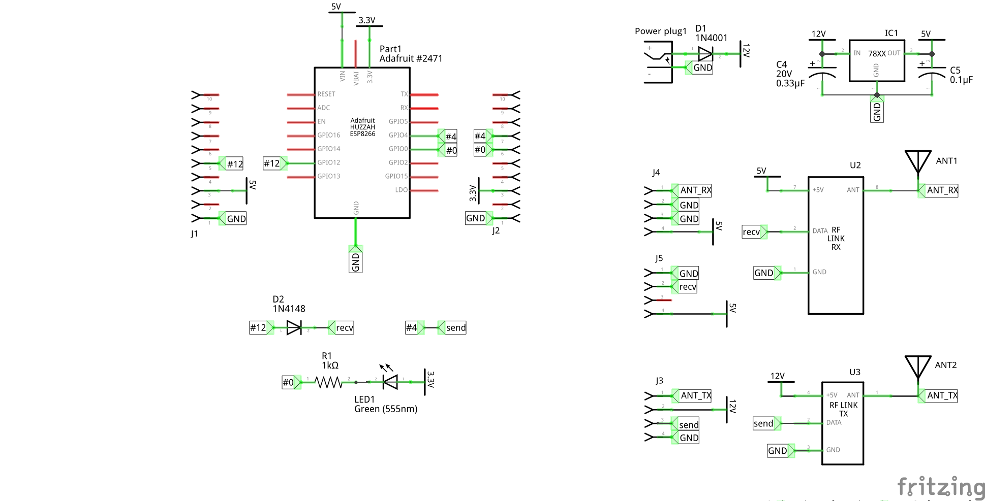
Current Setup:

I am ish-new to this stuff and have spent a few hours trying different setups and googling, but can find a solution. Thanks for your help!

I read in a post here by @puuu that I may need a reverse diode between the 5v receiver and the 3.3v nodemcu? I have a bag of them but am not sure which direction they should go? And if that’s the case would a 1N4001 work instead (that’s all I have).

Did you read the hardware part of the readme and had a look to the circuitry? Here D2 is connected with the cathode (side that is marked with a ring) to the receiver.

Any diode should be fine as long as the diode can handle 5V and can handle 1 MHz signals.

If you think the readme is not clear, please help with a pull request.

@puuu Thanks for the reply!

Hmm, I have hooked it up as specified and still don’t seem to have anything coming through. From NodeMCU D3 (GPIO 0; as specified in ‘rfReceiverPin’) -> [k]diode[a] -> RXB6 Data (pin 7).

I also hooked it back up to the Mega (running RFLink) quickly and it worked. Any other suggestions I can try?

This way is wrong. It must be: rfReceiverPin -> [a]diode[k] -> RXB6 Data

Also, please avoid using GPIO0, because it is used to select boot mode. If you do not want to accidentally enter flash mode at power-up, do not use this pin for input. I use GPIO 12.

Amazing. That seems to have done it.
I really appreciate your time and will go through the readme to see if I can update it to reflect/prevent the issue I had (although I’d caulk it up to inexperience).

Thanks again!

@puuu On a side note, now that it is working. I seem to just be getting only a lot of ‘random’ input (a few every second) such as:

Raw Log

RAW RF signal (6): c:012324;p:4019,322,190,663,6108@
RAW RF signal (6): c:001012;p:439,290,6046@
RAW RF signal (10): c:0012340104;p:546,384,677,1475,15415@
RAW RF signal (11): c:00012344445;p:983,4960,688,3813,228,6266@
RAW RF signal (7): c:0123415;p:1325,383,759,512,2738,6271@
RAW RF signal (19): c:01211345151561789:;;p:2101,185,551,1455,3359,907,2635,2944,740,1811,1194,6360@

When raw mode is turned off I get nothing. I am using devices that use the ev1527 protocol. When I activate the PIR sensor something shows up on the receiver. I seem to just be getting random input.

Additionally, when I pull the antenna out I seem to receive more shorter signals., but when I put it back they come in less often but are longer.

Are you sure that your PIR sensors are supported by pilight?

The raw log looks only like noise. I am not sure, if this is an problem of the 1N4001, I never tried it. Do you have a 1N4148 for testing? Other people report that it works without diode, you may have to disable rfReceiverPinPullUp in the web frontend. But be warned, the ESP GPIOs are only specified for 3.3V. On the other side, the datasheet of the RXB6 state that a supply voltage of 3.0V is sufficient, you may can try to power the RXB6 with 3.3V.

I have the same thing. When I put on ‘raw’, I receive a lot of transmissions, but neither my EV1527 or my impuls remotes are recognised.