Running slow on my side since my embed programming skills are way to old, but I will give some heads-up of my findings.
I’m using a ESP8266 but I guess others are kind of the same. I have done some findings in the original code but I have not concluded yet if those will have any real effect. There might be compatibility reasons, but just considering ESP8266 I’ve found this things in the code:
- The bus are in some (at least one) cases pulled high and that shall instead be left for the tri-state mode to let the pull-up resistor to pull the bus high. The main reason for this will be explained in the two next points.
- The code both changes pin mode (to input or output) and and also sets the pin high and low. This is not necessarily, the pin can be configured as low once in the initial phase and then we just need to configure the pin mode as output (for low signal since it’s already set to low in the initial phase) and input (for high signals since this will activate tri-state and then the pull-up resistor will drive the bus high).
If the bus is driven high from the ESP and low from the sensor (or vise verse), the bus will be in unknown mode and this by itself can cause instability.
- Considering the problem I will describe later in this post, operating more code than needed makes these issues worse. Saying this, I haven’t changed the code and can’t say if my findings will help, so far I’m struggling catching up my programming skills and understand and restructuring the code
- There code waits a predefined time for the temperature conversion. When not using parasite mode this is not needed, a better solution is the check the bus since devices will drive the line low while doing temperature conversion
- The code does not support parasitic mode and that is not the intention of the code either. But it doesn’t check if there are any sensors using parasitic mode and this could lead to instability. This is not mentioned in the documentation either
My main findings are that it’s very hard to create a reliable timing on the 1-wire bus with the ESP8266 using the code framework that the ESPHome Dallas Component is based on. I will attach some pictures below showing what I mean
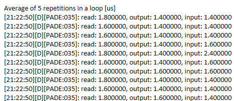
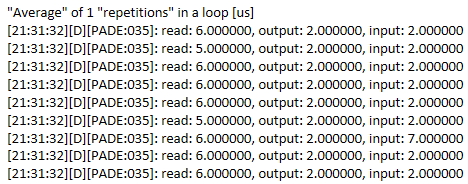
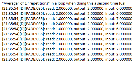
I started to test the accuracy of the delayMicroseconds() function used in the code and since I couldn’t get a stable reading on my oscilloscope I decided to create my own using a loop of instructions and I decided to go for the read-pin function. Repeating the read instruction 200 times gave an average of ~0.67 us per read instruction. I then decreased the count to 1 time and got an average of 5 and sometimes 6 us per read. My thinking was the this depended on some overhead in my time measure and loop but just to verify I decided to check the average read-time twice in a row and then it was down to 1 or 2 us.
Doing the same test with pulling the bus low and releasing the bus into tri-state the average was ~1.3 us for both of them. Decreasing to 5 times gives an average of 1.4 us per instruction but sometimes an average of 2.4. Decreasing to 1 time gives an average of 1 to 2 us but sometimes as high as 7 us.
Now looking at the oscilloscope pictures below. Ignore the pattern generated but compare the two pictures. Note that the timing (x-scale) is quite high (20 us per division) so also smaller differences matters.
The delays here are generated by repeating the instruction, e.g. if I pull the bus low I repeat the same instruction 4 times. The first bus-low instruction is happening at the very left of the screen. The first release line is happening at the first division mark in both picture’s, but then the second bus-low is happening 4 us later in the upper picture compared to the lower picture. In the upper image we also se some “shadows” indicating the instructions sometimes taking longer time.
And before someone asks, Yes I have turned of the interrupts. But… I haven’t seen the low level implementation of the code that shall stop the interrupts (just the virtual constructors) so I’m not sure it works.
Also attaching this picture below (now time scale is 5 us per div) showing a shadow sample being 9 us away from its average
I don’t think it’s the ESP-chip that is the problem here (and @gedger indicates the same), I rather suspect that it’s in the low-level part of the code (i.e. not the part of the code that was written by the developer of the Dallas component for ESPHome)
So does this matter??? I would say yes, at least looking at the timing in the current code where an additional 5 us sometimes could be a disaster. Please note that I haven’t verified if any of this will help though…
Looking at the timing below:
To determine if the reading is a 1 or 0, we have 15 us to read the bus after the bus has been pulled low by the ESP. In ideal conditions (my bread-board) the pull-up resistor drives the bus high in 2 us but in real situations having capacitance added by sensors and cables this can be much longer. The spec allows this to take 15-1=14 us.
The dilemma:
If the sensor wants to deliver a zero and we (due to extra delays) waits to long, the sensor will already have released the bus into tris-state when we are reading and hence we will read a 1. But on the other hand, we can’t read to fast either because if the sensor wants to deliver a 1, we might (if we are reading to early) read while the pull-up resistor is driving the bus high (but before the signal is high enough to register a 1.
So what can we do??? I guess the best would be to read the line as fast as possible but not faster than the rise-time on the 1-wire bus. So how can we know the rise-time of the 1-wire bus since it changes depending on the number of sensors, length and characteristics of cables, etc. My idea is to use the reset pulse described below to calculate the rise-time:
If we initiate the reset pulse and measure the time it takes until we read a high value and then add some micros seconds just to be safe, we probably get a good indication of the system. Let’s say we do this in the startup phase 200 times, calculate the average and then add (lets say) 5 us. If the value is lower than 15 us we are good to go and I expect that we will get a much lower value than 15 us. We can also use other methods like broadcasting for the ROM code and for each bit received calculate the average time for a 0 and the average time for a 1. The second solution is probably best since we can get timings from more than one sensor (kind of random but anyway…) but requires that we have the correct timing to even write to the bus. So the two methods probably needs to be combined.
But the best method (if available using ESPHome code) would probably be to fix the base code for the pin configurations so that we can control the bus with the accuracy that is required and that @gedger indicated that we could do using Arduino.
Lets see what some evenings, nights, and early mornings will lead to…
For reference. Average execution time for Reading the bus, Setting the bus to low by setting the bus to Output mode, Setting the bus to high by setting the bus to input (tri-state) mode.


