Nice! If you have extras, you could send your best buddy Justin one of them!! ; )
If you use it to cut power alone, im not sure off the top of my head how you would re-enable the power if the limit switch is held down becsuse it stopped on it.
I would just do it in code. Configure them as binary_sensors and put the automations on the esp itself, not HA.
Just easier for my brain and the forum is nit jelling at me all the time for using the wrong ‘’’
Quick question ot the side. Can u think of any reason why my binary switches when triggered toggle all the time? I dont get a steady on or off when triggered…which defeats the purpose of an inidactor is door opened or not. And i still have a very unrealiable reporting off lsw2. Awkward
Is it maybe due to the delay on and delay off that i put in there whithout knowing what they do?
is correct to expose the status of the 2 switches on boot?
Or is that already done in the binary sensor with the publish_initial_state: true that i have in there?_
What makes you think they’re not exposed on_boot? If you dont know for sure, the easiest way to figure out the answer is to just reboot it an watch the web_server or watch HA to see if theh display the correct status.
You need to show us pictures of how you setup these sensors in relation to the moving door. You also need to post a picture of your log output so we can see how they are acting when they are triggered by the physical door hitting them.
You have to post more specific details and not just verbally describe things. Help us be able to help you!
That is unless its Karosm helping you then do as you please because the rumor is that he likes the pain and likes banging his head against his desk!
Im not even close to being convinced that it isnt the door itself thats causing it. If its too lose and stops quickly on top of that limit switch then it will likely bounce On/Off and even though I’ve already asked him atleast twice to share some details and/or photos of this contraption, he has yet to do it and this post that should be a simple fix, it keeps going on and on and on and not just here but Reddit and i think FB too…
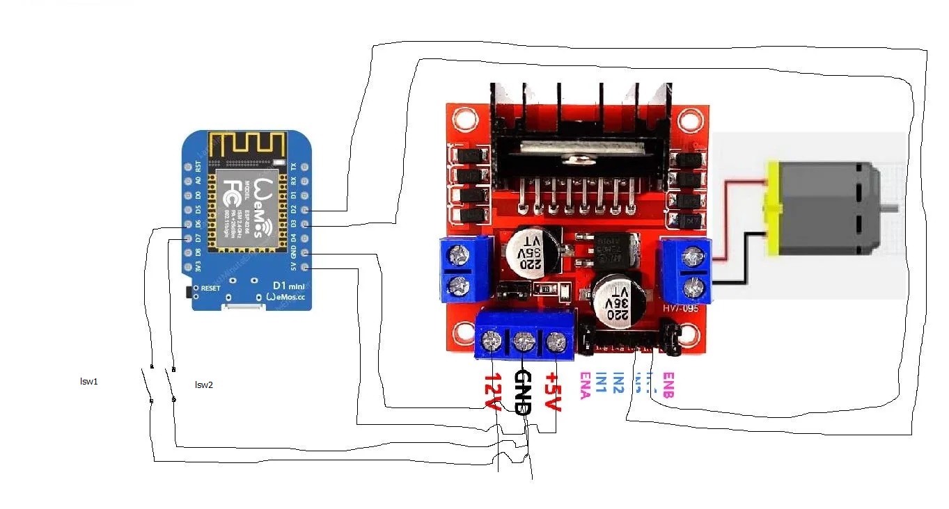
Chickendoor|690x370
This the build with lsw1 being physically closed until door reaches top/open and lsw2 being physically closed until door reaches bottom/closed
I tried remotely just now to get the logs, but the stupid door got stuck,so i cant show the binary sensor changes right now, but will deliver later.
We had tons of rain the hole spring and this door frame is constantly swelling…another project to work on…
Thx a lot for your attempt to help…highly appreciated…
What do you mean with i need pullups? you saying physically add 2k resistor in line with each of them? Could that missing resistor cause the strange on/off jumping jacks?
I don’t have an active FB account. but being desperate cause i thought i was doing something good by swapping from 2 relay esp01 board to an h bridge…but so far it was a nightmare…but i always share the results when something finally works out and share the code, so that the next doesnt need to go through the same hassle.
Of course. When your switch is closed, it’s pulled to LOW.
When you switch is open, it’s what? HIGH? LOW? Something between?
Internal pullups work for short wiring, but not necessarily for long.
Desperate eehh??? Desperate enough to give a grown man a foot massage if that man has the answers you seek???
Lol jk!
Ya, that switch wouldn’t have been one i made but, it’s doable. Thats another reason for including photos of the hardware system so that you can benefit from others giving you pointers or tips so that maybe you dont have to make the mistakes they made in the past or they have much better or easier to build ideas than what you came up with… These are positive things that you should want. I know that over the years ive made many mistakes and wasted money. If only i had sought after peoples input beforehand then maybe i could have made far few mistakes, wasted far less money, wasted far less time redoing things over and over by putting my stuff out there for others suggestions or even criticisms sometimes but, thats how we all learn and get better!
I am the last to complaining about critic…i have no false pride in that direction.
All i want is my ladies being safe at night and happy outside at daytime with the least user intervention possible. Went from dumb light senor setup with an old automatic car antenna, to semi smart with esp01 double relay board and gear motor to now this hbridge in hope to get informed when door does for some reason not open or close in the morning or night…have a local button to toggle open/close to not always have to carry my phone around and that’s already about it…some of the hardware is, because of that, historically grown and probably not the most sophisticated or professional…
So when i get home today, i will make pictures and hopefully soon, get 2 2k resistors into the switch lines…they just need to be in line, correct? no extra crossing to power or data lines?
No they are not in line. They are resistors you place between Esp 3.3V and binary sensor GPIO pin. So the binary sensor has HIGH state when the limit switch is open. Makes sense?
For best support, post all your wiring and show your switch setup…
And when you are ready to post your actual yaml with code tags, feel free to do it as well…