Do you mind shipping your cable / adaptor etc to me ? so I can validate everything is fine.
Then we know cable is good.
Do you mind shipping your cable / adaptor etc to me ? so I can validate everything is fine.
Then we know cable is good.
Which com port was generated by the FTDI adaptor ? might need to scan for extra com port on Nikobus software?
No, it is not a problem
ok, so or the PCLink is broken, or the cable is bad. I can check the cable for you, ship it to
Cable, adaptors, everything you have between PC and PCLink
Frederic Debrus
Avenue Princesse Paola 13
1410 Waterloo
Hi fdebrus,
Thank you so much for your offer to test the cable and adapter yourself — that is incredibly generous and we are taking you up on it.
Before we send everything, one last question we wanted to check with you first: on our DB9 female screw-terminal adapter, we added two hardware jumpers:
These were added early in the process to satisfy the hardware flow control requirements of the PL2303 adapter. We kept them when we switched to the FTDI adapter.
Could these jumpers be causing a problem? Is it possible that the PC-Link uses any of these control signals (DCD, DTR, RTS, CTS) for something specific, and that shorting them together could prevent communication?
We want to make sure we are sending you the setup exactly as we have been using it, so you can reproduce what we see. We can remove the jumpers before sending if you think that would be better.
Thank you again!
Jean
I should not have any influence. Nikobus is dump, remove everything and keep those 3 TX / RX / GND
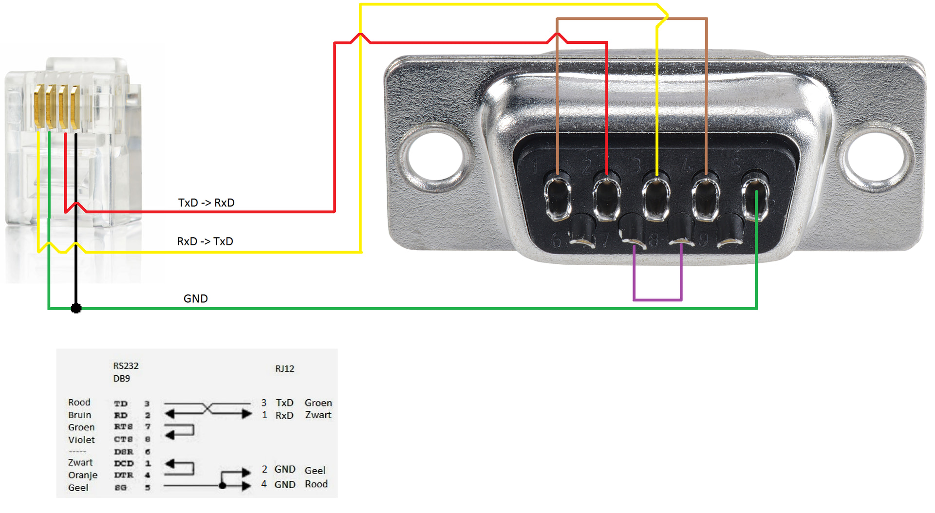
FTDI pin 3 (TXD, out) ─────────► PC-Link RXD (its input)
FTDI pin 2 (RXD, in) ◄───────── PC-Link TXD (its output)
FTDI pin 5 (GND) ─────────────── PC-Link GND (signal ground)
Hi fdebrus,
Before sending you the cable and adapter, I wanted to share the reasoning behind our wiring so you can confirm whether we understood your instructions correctly.
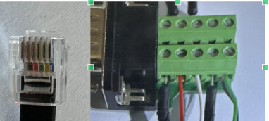
RJ12 cable (6P4C, clip facing away, numbered left to right 1→6):
When clipped into the PC-Link 05-200 (which only uses 4 of the 6 pins as per the 05-200 manual), we assumed that the outer pins (White=1 and Blue=6) are not connected, leaving the 4 active pins as:
On the DB9 female screw-terminal adapter, based on your pinout table, we connected:
We also added two jumpers on the DB9 adapter:
Regarding the PC-Link LCD, it displays three indicators that we believe may have diagnostic significance:
The LED blinks on every button press, confirming the Nikobus bus side is working fine.
Does this wiring look correct to you? We want to make sure we haven't made a fundamental mistake before sending you the hardware.
Thank you!
Jean
I think we've got it, and it's good news: your PC-Link is very likely fine the issue is the cable mapping.
I cross-checked against the known-good reference cable (the mForge RJ11↔DB9 one). It specifies the PC-Link's four contacts, in order, as:
RxD · GND · TxD · GND → RJ pin 1 = PC-Link RxD, pin 2 = GND, pin 3 = PC-Link TxD, pin 4 = GND.
And on the DB9 side:
So your two jumpers are correct keep them, they match the reference exactly.
The problem is the RJ side. You assumed the active contacts are the middle four (2–5) of the 6-position plug, but the reference numbers the PC-Link's four contacts 1–4 so your mapping is shifted by one pin. On top of that, flat RJ11 cords are usually rollover cables (the pin order mirrors end-to-end), which can reverse things again. The net effect is that your TxD and RxD have been landing on the wrong PC-Link contacts and in the worst case the PC-Link's own RxD (its pin 1) is the contact you assumed was unused, so the PC could never send it anything. That produces exactly the silence you saw, including "PC-Link component not detected", on a completely healthy unit.
Tu as raison — un document Word n'est pas idéal pour un forum. Le plus simple serait de poster directement en texte formaté dans le forum HA, qui supporte le Markdown.
Voici le contenu complet prêt à copier-coller directement dans le forum :
Nikobus PC-Link 05-200 — Diagnostic update for fdebrus
1. Hardware 3× switch module 05-000-02 (12ch), 1× switch module 05-008-02 (4ch), 30× push buttons 05-064, 1× PC-Link 05-200. PC-Link LCD: "M" line 1 / date + "0" line 2 / time + "A" line 3. LED blinks on every button press — bus is healthy.
2. RJ12 cable wire colors (6P4C flat, clip away, left→right 1→6)
| Pin | Color | PC-Link function |
|---|---|---|
| 1 | White | PC-Link RxD |
| 2 | Black | GND |
| 3 | Red | PC-Link TxD |
| 4 | Green | GND |
| 5 | Yellow | Not connected |
| 6 | Blue | Not connected |
3. DB9 screw-terminal adapter wiring
| DB9 pin | Signal | Wire color | RJ12 pin |
|---|---|---|---|
| 2 | RxD (PC in) | Red | 3 (PC-Link TxD) |
| 3 | TxD (PC out) | White | 1 (PC-Link RxD) |
| 5 | GND | Black + Green | 2 + 4 |
| 1↔4 | DCD↔DTR | Jumper | — |
| 7↔8 | RTS↔CTS | Jumper | — |
All connections verified with a multimeter — continuity confirmed on every wire. Photos of the DB9 wiring are provided below in the same format as your reference diagram. I tested from my server side and also direct on the nikobus with the official program on Windows 11
4. Result FTDI FT232R (genuine, Farnell). Length mismatch / bit flip completely gone. But still NikobusTimeoutError on all commands.
Could you confirm whether our DB9 wiring is correct based on the mForge reference?
Thank you! — Jean
Hi fdebrus,
After weeks of troubleshooting, I have decided to close this thread — not because we have given up, but because I feel I have already taken far too much of your time, and you have been incredibly generous throughout this journey.
The situation is now clear: the issue lies either in the cable or in the PC-Link itself. I am going to order a new RJ12 cable (found some on Alibaba) and test again. If the cable is not the culprit, I will need to think about what to do regarding the PC-Link.
Whatever happens next, I want you to know that your support has been exceptional. Your bit-level frame analysis, your pinout corrections, your patience with all our questions — this is exactly what makes this community so valuable. This project means a lot to me: integrating a 20-year-old Nikobus wired installation into Home Assistant would be incredible, and we got much further than I ever expected thanks to you.
I will post an update if and when we finally get it working — I hope to come back with good news!
Thank you from the bottom of my heart, fdebrus. 
Jean
Thanks for the pictures is helps 
your DB9 side is wired correctly the issue is which RJ contacts you're using. Let's confirm it with a meter instead of pin numbers. Please do these 4 steps in order:
Step 1 Find the 4 real contacts
Look straight at the RJ plug. On a 6P4C, only the middle four slots have gold metal; the two outer slots are empty. So your active contacts are the middle four, not "1–4." (This is likely the whole problem the numbering got shifted by one.)
Step 2 Find the PC-Link's TxD by voltage (the key test)
 If no contact shows a negative voltage → the PC-Link's serial transmitter is dead. If one reads negative → good, it's alive. Continue.
Step 3 Wire it by function (not by number)
Step 4 — Test
Run the official Nikobus software, direct connection. If it connects, Home Assistant will too (9600 8N1).
The −5 to −12 V reading in Step 2 is the decider: it tells us in one measurement whether the PC-Link is alive and which contact is TxD. Let me know what voltage you get on each contact.
We will get you sorted, late reply as I'm on business travel...
Should be
| Pin | Color | PC-Link function |
|---|---|---|
| 1 | White | Not connected |
| 2 | Black | PC-Link RxD |
| 3 | Red | GND |
| 4 | Green | PC-Link TxD |
| 5 | Yellow | GND |
| 6 | Blue | Not connected |
Hi fdebrus,
Great news from Step 2!
With the cable connected directly to the PC-Link only (FTDI unplugged on the PC side), measuring DC voltage with black probe on GND (DB9 pin 5):
DB9 pin 2 → +7.73V (PC-Link TxD — alive and transmitting!)
DB9 pin 3 → +0.15V (PC-Link RxD)
So the PC-Link serial transmitter is alive. Our current wiring has pin 2 as RxD (PC in) ← PC-Link TxD, which matches this measurement.
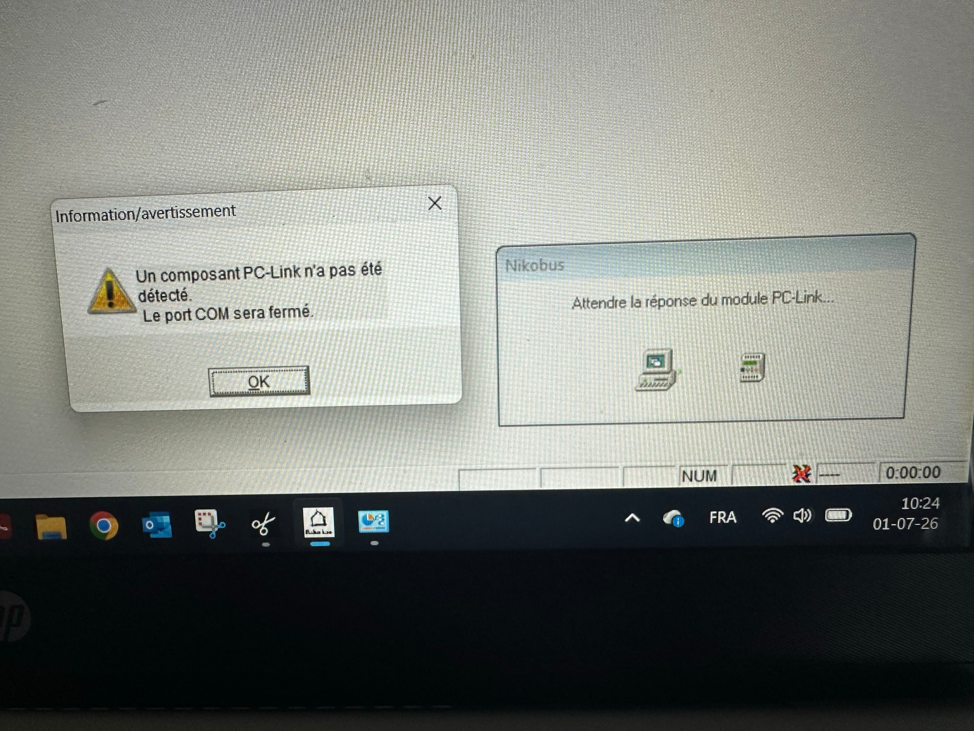
Yet the official Nikobus software still shows “PC-Link component not detected” when connected directly with a short cable. What could explain this if the PC-Link TxD is clearly active?
Thank you for staying with us despite your business travel — we really appreciate it!
Jean
PS : Additional measurement with the FTDI adapter completely removed from the DB9 (only the RJ12 connected to the PC-Link, probes directly on the DB9 screw terminals):
DB9 pin 2 → +8.68V
DB9 pin 3 → 0V
The voltage on pin 2 does not change when I press a push button. I notice the voltage is positive (+8.68V) rather than the negative value (-5 to -12V) you mentioned. Could this indicate that the PC-Link is using TTL logic rather than true RS232?
Have you tried this ?