Thanks Rob, I will have to ask the father in law later he is a sparks but sadly he’s pretty anti Home automation, just simply doesn’t see a point so I usually get little feedback or negative … but i see exactly what you are saying essentially the existing wiring to the switches becomes purely a method to interact with the GPIO, this is pretty eligent, I could potentially get one of the multi channel versions and control a couple instead of a one to one, i Am assuming the only issue with this would be that as it’s a single GPIO the switches would have to be all or nothing, as it would not be able to differentiate the source to invoke a different action on the output.
I not sure what you mean but I think you can program the gpio to react to a quick on off on off as one switch and on / off as another so one switch has two functions.
Sorry, what I meant is my living room for example has two lights and two switches they are currently independently controlled, toggling one switch has no effect on the other light I guess if I was to use one Sonoff each switch would end up controlling both lights, this isn’t neccaserly a preference it’s just how it has always been and just trying to plan what I need and expect before hand.
I think you will need a sonoff for each light you want to control as each sonoff has one relay.
Yep, that looks right, this was my explanation with diagram of how to use a single Sonoff with one, two and three way circuits in the UK…
Hi all,
just came here after watching the video.
I have a maybe silly question: I’m not able to sold wires and I don’t feel confident on hacking the hardware.
Do you think I can avoid the neutral hack by using the sonoff POW model (who already has neutral wire) to add it inside my wall switch box?
Thank you all in advace!
Not sure where you’re coming from but you need a neutral for all Sonoffs and you’ll have to do some soldering if you want to use the original or other external switch.
Hi!
I came here from the original post at the top. 
The POW Sensor has a neutral in built. Please look at the following image found on ITEAD website
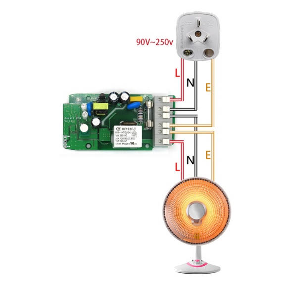
So I was wondering if with this product I can avoid soldering and use my in wall switch.
Thank you!
Yep, exactly the same as the Basic, it’s just input at one end, output at the other, rather than all at one end. The POW does have earth connections on the board which the Basic doesn’t but that’s not really relevant to this.
OPS!
You’re right.
Damn. I don’t want to burn down the house 
I was able to get a single sonoff to control a 3 way light (2 switches controlling 1 light). Basically what I did was put the sonoff in the box that had the wire that went up to the light, hooked up that light switch as a GPIO 14 input on the sonoff. Then I converted the tx pin (serial out) to GPIO1 with use of 4.7k resistor, and used the traveler wire running to the second switch as an input to GPIO 1. It works perfectly. I have pictures and a wiring diagram and I’ll try and post a nice write up on how I did this.
1 Like
This is my approach to get 3 sonoff in the wall. To mention is maybe that this will be the kitchen and I won’t see it as there will be a furniture in front of it


2 Likes
nicely done!
I found this nice single gang box on thingiverse:
https://www.thingiverse.com/thing:2830060

So here’s how I wired up a 3 way (US) 2 way (UK) light using a single sonoff.
It assumes that your 3 way light was setup in a specific way. The following things need to all be coming into one wall box
- Power from breaker box
- dedicated wire to light
additionally your traveler wire needs to do NOTHING but run between the two wall boxes
- dedicated traveler wire to the second switch
Modifications to sonoff:
- 2 conductor 26awg wire soldered onto GPIO 14 & ground pins
- 4.7k resister connecting 3.3v to the TX pin, along with another 2 conductor 26awg wire with 1 conductor connected to TX (along with the leg of the resistor) and the other connector going to ground.
It’s very important that you verify that your wiring configuration is setup identically to this, or things will probably go up in smoke. An inductive voltage tester is pretty handy to help make these determinations.
So we are going to call Box1 the main box, with power in from breaker box, wiring up to light, and one end of the traveler wire.
Box 2 will be the wall box that has a switch and the other end of the traveler wire in it
Box1:
- Connect the black & white wires from the breaker box to the input of your sonoff.
- Connect the black & white wires going to the light to the output side of the sonoff.
- Connect the switch to GPIO 14 & ground of the sonoff (I find that tinning about 2 inches of the end of the 26awg wire makes using the switch screw terminals, which were designed to accept 12-14awg solid wire much easier to use)
- Using a couple of wirenuts connect the second pair of 26awg wire to the red & black wires of the traveler wire. Again, about 2 inches of twisted and tinned ends make wirenutting 26awg wire to 14/16 solid wire much easier.
Box2:
*Connect the red/black wires to the switch
Setup the sonoff
- GPIO14 is set to “09 Switch1”
- GPIO1 Serial Out is set to 10 “Switch2”
Now, make sure both switches are in the “off” position and turn on power at the breaker. Changing either switch from on to off or off to on will result in the light toggling state. Basically we set it up like we would a normal sonoff, then use the existing traveler wire, that previously carried the high voltage, into another low vlotage GPIO switch.
Here is a pretty basic diagram showing what I did, along with the modifications to the sonoff.

1 Like
Nice work! Two switches toggling the various GPIO pins. I like it! I’ve been using 10k resistors on my standard single switch installs in the wall box to prevent ghost switching. I’m no expert on the values used and just go by what others recommended. Should I use 10k or 4.7k? Shouldn’t I also use it on the GPIO 14 switch of this setup? I don’t get the ghost switching all the time but after I had an issue with a couple of them I threw in the GPIO14 10k pullup on all of mine now.
Is the sonoff basic really rated at 10amps for 110/120V users in USA? It looks to me since the input power is rated from 90V to 250 VAC and the maximum power is rated for 2200W, ITEAD chose 10 amps max. I assume 10 amps was based on 220/250VAC users. For 110V it should be more like 18 amps or so. Correct or I am just going haywire?
I’m not sure about the difference between 4.7k and 10k. It’s been a long time since my circuit design and analysis classes. But I do remember we always used 4.7k as pull-up/pulldown resistors, and since I had a ton of them hanging around, that’s what I used.
From my understanding, GPIO 14 already has an internal pull-up resistor attached to it, so you do not need to add another one. I never add one to GPIO 14 and have yet to have any issues.
Yep, that’s what I’d read ![]()