A quick sanity check please. I can achieve the exact same with this module, main difference being only s common ground and signal going to the MCU, right?
Thanks!
A quick sanity check please. I can achieve the exact same with this module, main difference being only s common ground and signal going to the MCU, right?
Thanks!
Hi, all
I have attempted same setup, but something weird is happening with MOS. When fan is not connected to MOS module output the slider button in HA can turn MOS module on and off. I can see 12v on the power input side and on the output side. As soon as I connect 12v output side to the fan voltage drops below 1v. As soon as fan disconnected - 12v is there again.
Any ideas?
Asking a very slightly different question here. If using an ESP8266, with esp8266_pwm, how can we define a fully autonomous ESPHome device, that sets the fan speed according to the value of a DHT22 temperature sensor? In other words, keep the speed control completely within the ESPHome device, rather than depending on an HA automation.
Here is my final YAML code. I have omitted MED, HIGH, and MAX template definitions for brevity.
For my use, OFF = 0%, LOW = 25%, MED = 50%, HIGH = 75%, and MAX = 100%.
I’m certain there will be some temperature range tweaking in my future.
switch:
  - platform: template
    id:       fan_speed_off
    turn_on_action:
      - logger.log:
          format: "The temperature sensor reports value %.1f, fans OFF"
          args: [ 'id(rack_temp_f).state' ]
      - output.turn_off:
          id: fan_power
      - fan.turn_off:
          id: fan_pwm

  - platform: template
    id:       fan_speed_low
    turn_on_action:
      - logger.log:
          format: "The temperature sensor reports value %.1f, fans LOW"
          args: [ 'id(rack_temp_f).state' ]
      - fan.turn_on:
          id:    fan_pwm
          speed: 25
      - output.turn_on:
          id:    fan_power

    temperature:
      id:   rack_temp_f
      name: "Rack Temperature"
      unit_of_measurement: "°F"
      filters:
        lambda: |-
          return (x * 1.8) + 32.0;

      on_value_range:
      - below: 75.0
        then:
          switch.turn_on: fan_speed_off

      - above: 75.1
        below: 77.0
        then:
          switch.turn_on: fan_speed_low

#
# fan_power  is a relay switching 12VDC fan power on and off
# pwm_output is a speed control line to the PWM fan
#
output:
  - platform:  gpio
    pin:       D5
    id:        fan_power

  - platform:  esp8266_pwm
    pin:       D6
    frequency: 20000 Hz
    id:        pwm_output

#
# The fan object
#
fan:
  - platform:    speed
    id:          fan_pwm
    name:        "Rack Fan PWM"
    output:      pwm_output
    speed_count: 100
    restore_mode: ALWAYS_OFF
Found a good YAML example in this Github repository. Got me thinking how to do it.
This thread was what I actually needed. It uses template switches to set the output speed percentage 
Hi! all
I have exactly the same situation.
I have power supply:
Here you can see 2 code snippets, how I’ve controlled MOS module
The first try
output:
  - platform: ledc
    pin: GPIO19
    frequency: 100 Hz # also there were values 500 Hz, 1000 Hz, 10000 Hz
    id: ventilation_fan_pwm

fan:
  - platform: speed
    output: ventilation_fan_pwm
    name: "Ventilation Fan"
This is second try
output:
  - platform: esp32_dac
    pin: GPIO25
    id: dac_output

fan:
  - platform: speed
    output: dac_output
    name: "Ventilation Fan"
In both cases I have same result:
Does anybody have an idea what is the reason and how to fix this problem?
Could it be the Mosfet you picked? I believe that for current to flow at the Mosfet’s rated capacity you have to turn it on with the right voltage. Many Mosfets still turn on at 3.3V but they are not able to provide the full current the fan may require. By picking a Mosfet that is compatible with 3.3V logic you should be ok, or you need an extra transistor (for example) in between to increase the voltage. Hopefully I relayed this correctly as I researched this a while back.
Edit: I found that the IRF520 requires 10V to be fully (max current) switched on. In my projects I ended up using an SMD mosfet mounted on a small adapter perfboard as I could not find through hole mosfets with enough current that had a 3.3V logic level gate threshold.
I have a same problem.
this module has " * Tensione di pilotaggio: 3,3-5V"

the out of 8266 is 3.3v
how can i fix it?
No need to fix it. The module accepts from 3,3VDC to 5,0VDC.
Hi fellow @corvy, Did you achieve smooth fan speed control with the slider ?
Or do you only have 3 speeds and fan off ?
I have exactly the same stuff as you i.e. ESP32 with esphome and a board with irf520
Are you able to help me ?
Thank you
Hello! I got 3 speeds and off.
I understand, and someone has succeeded on this circuit to create a variable speed control of 12V fan ?
Hi Can you share the code that gives you the low, medium, high?
I think they deprecated the speed: command but please let me know how youre doing it.
Thanks,
Joe
The gate barely let’s any current through at 3.3v or 5v. Telling people that the irf520 accepts those logic levels is horrible advice and it’s just wrong. You may be able to get a crappy little fan to work when it uses very little current but when someone needs to conduct multiple amps through that fet they won’t be able to and it’s going to be a nightmare for them troubleshooting it because you told them flat out wrong information.
Hi @robbie21 !
I‘m having the same issue like you with no speed control if using 20kHz.
I’m using D1 Mini which has ESP8266, 12V fan and mosfet.
I got nearly 12V on my fan regardless of duty cycle.
Because datasheet offers max pwm frequency for esp8266 is 1kHz I‘m thinking to replace it by using esp32.
If I measure directly on pwm pin with my rms multimeter it shows 1,65V at 50% duty cycle and 20kHz so I‘m not sure this is really the problem.
Anyhow I haven’t an oscilloscope so I don‘t know exactly how the waveform looks like.
So did you replace your esp8266 with esp32 and did that fix your problem ?
If you can’t get any speed control, switching to an esp32 isn’t going to change anything. The hardware pwm on the esp32 has a better resolution(technically) and it’s better in certain cases where it’s “noisy” the hardware pwm is better, but for most things you can’t see the differences with the human eye. The fact that you have no speed control suggests you have something wired wrong, the code is wrong, the hardware is wrong. So, your using a mosfet? That’s really helpful. What’s the Vgs? min/max? is it logic level? are you using another transistor as a gate driver? 9 times out of 10 this is because you’re using the wrong fet and the gate can’t be driven by an esp board alone, the 3.3v wont open the gate or will only barely open the gate.
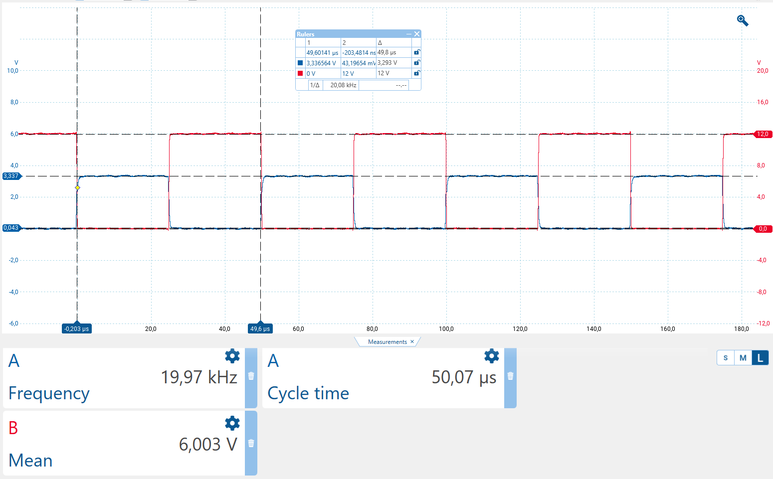
I just made a measurement with a scope and now I can tell you that 20kHz with D1 Mini (ESP 8266EX) is not the problem…
Here you have a measurement directly on the pin where I set up 20kHz pwm (50us) and 50% duty cycle.
I’m using logic level mosfet IRLZ44N connected to a gate driver TC4427A.
Circuit looks like this (not sure about real values on R + L of the fan).
I also made a few measurments in my circuit.
Channel A - Ugs
Channel B - Uds
20kHz 50% Duty Cycle
Same conditions but measurement over the fan (between 12V - Uds)
For me it looks like the freewheeling diode doesn’t becomes conductive fast enough ?
Same measurement over the fan but now 100Hz pwm with 50% duty cycle.
what type of fan is this? have you had these fets working anywhere else? There’s lots of knock off components out there. I’m not familiar with that gate driver, have you tried bypassing it? Are you able to drive the load with just the fet and esp board? might be “process of elimination” time.
It’s a 24V fan (2 pin): Papst TYP 8414 NG
Yes but no essential changes.
Here I made some measurements without the gate driver.
First of all with an omic load, here everything looks quite well:
Uds and Ugs at 50% and 20kHz
Same measurement but here with the fan connected again (also without the driver):
So for me it looks like the inductive load or the fan itself is the issue here ?!
Should I try another fan or is fast switching with 20kHz impossible with such a simple 2 pin fan ?
Maybe because of the electronic (to commutate the motor wires) on the fan they aren’t made for pwm and allways a constant voltage is needed ?