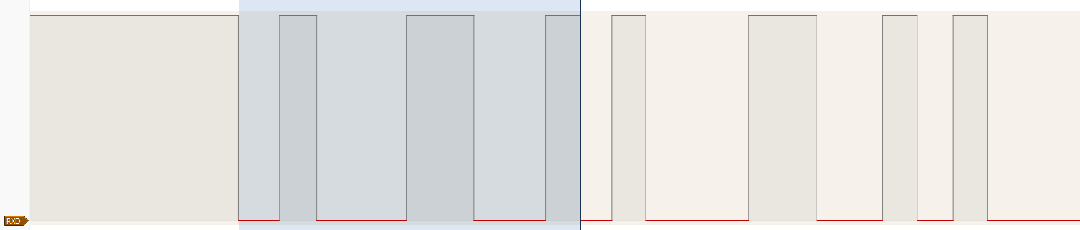
Ok, the protocol issue seems to be solved - so basic! ASCII, Serial 1200,8,1,N. Just need to discover the voltage levels to drive everything, hopefully transparently so that there is no need to modify the remote or main board.
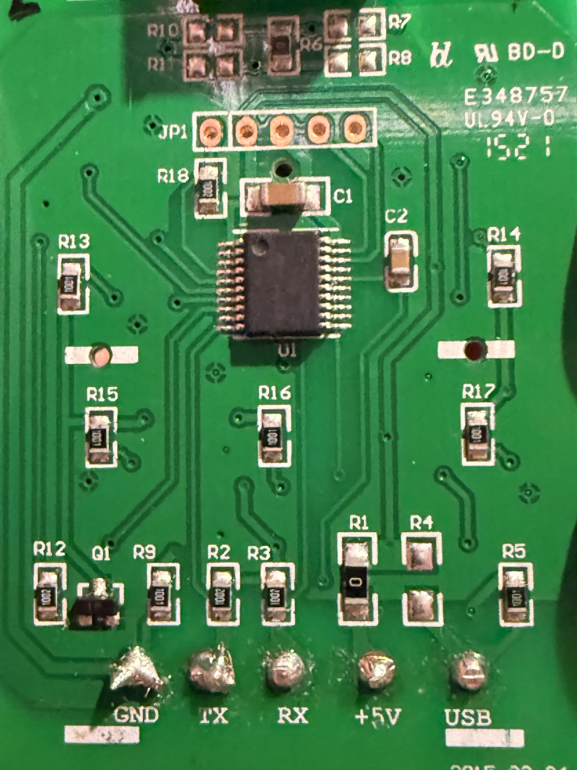
Tracing the connection from the remote, both TX and RX, through to the main board, what resistors and semiconductors it passes through till it gets to the PIC should be the final part of getting this reverse engineering process solved.
We’ve excluded the ULN2003A driver chip from the control chain from the remote, so the bridging of the two resistors on the remote going to the TX and RX pins become important.
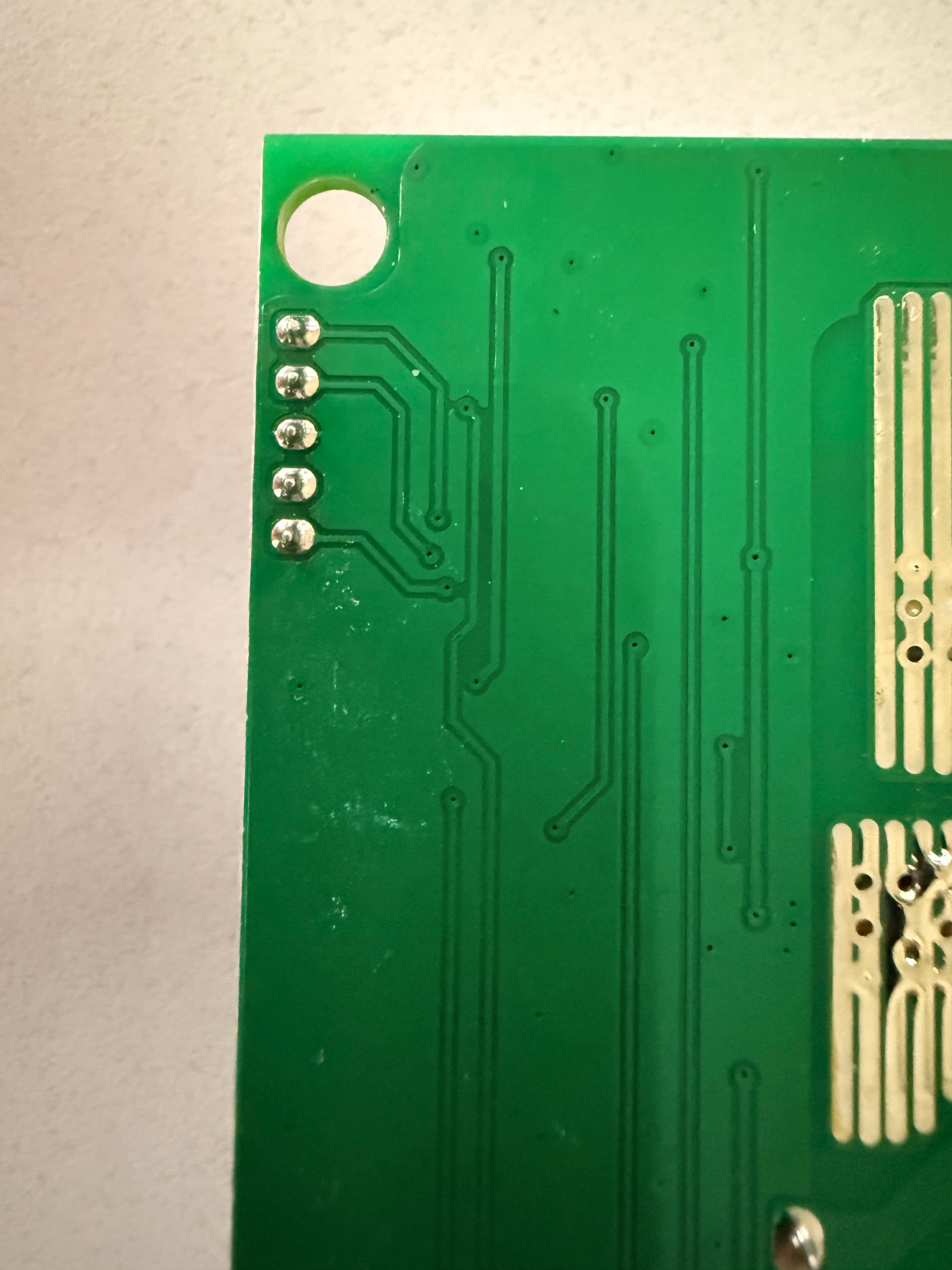
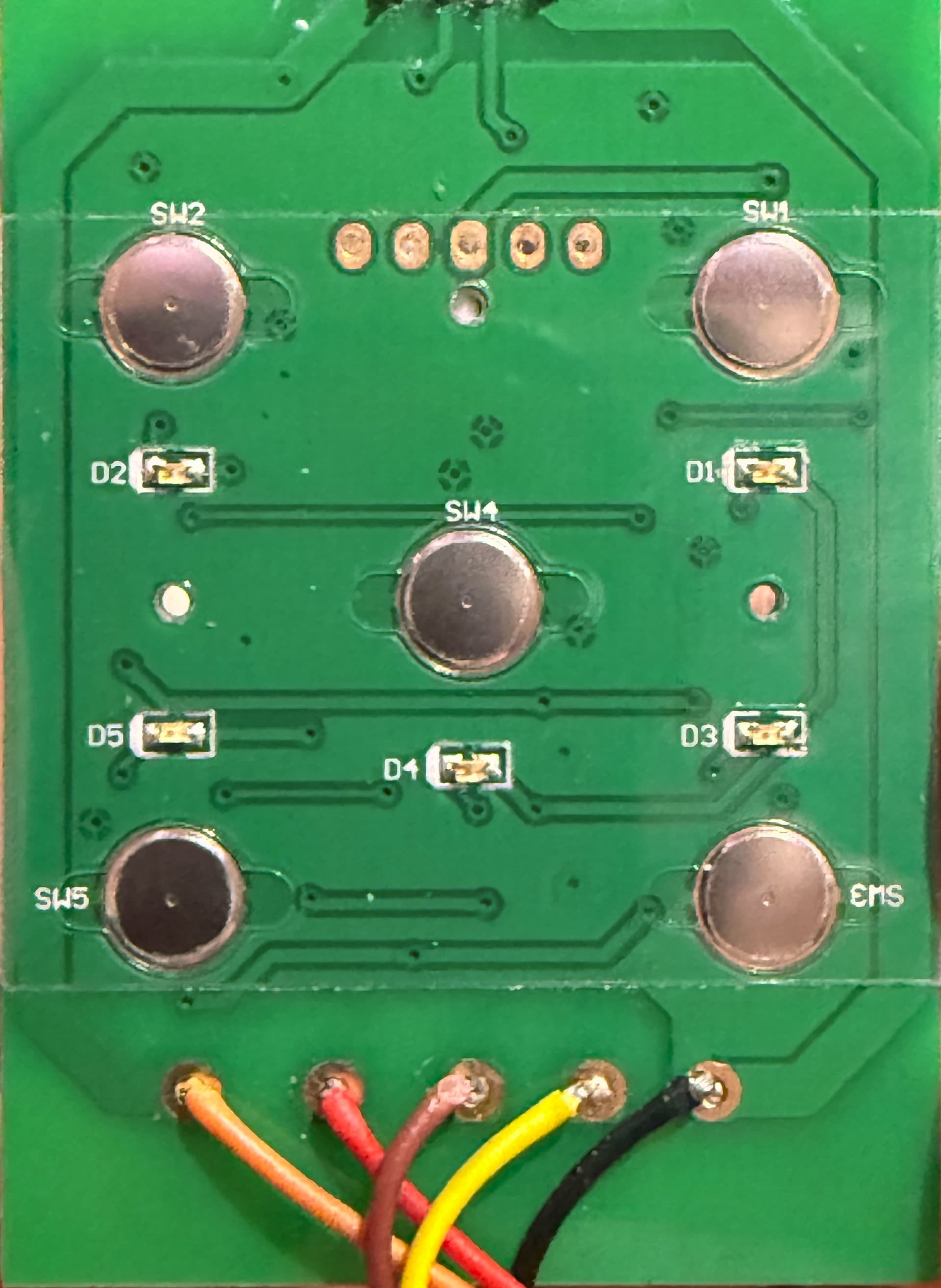
Can we have a peek on the other side of the remote board if possible, especially for any semiconductors?
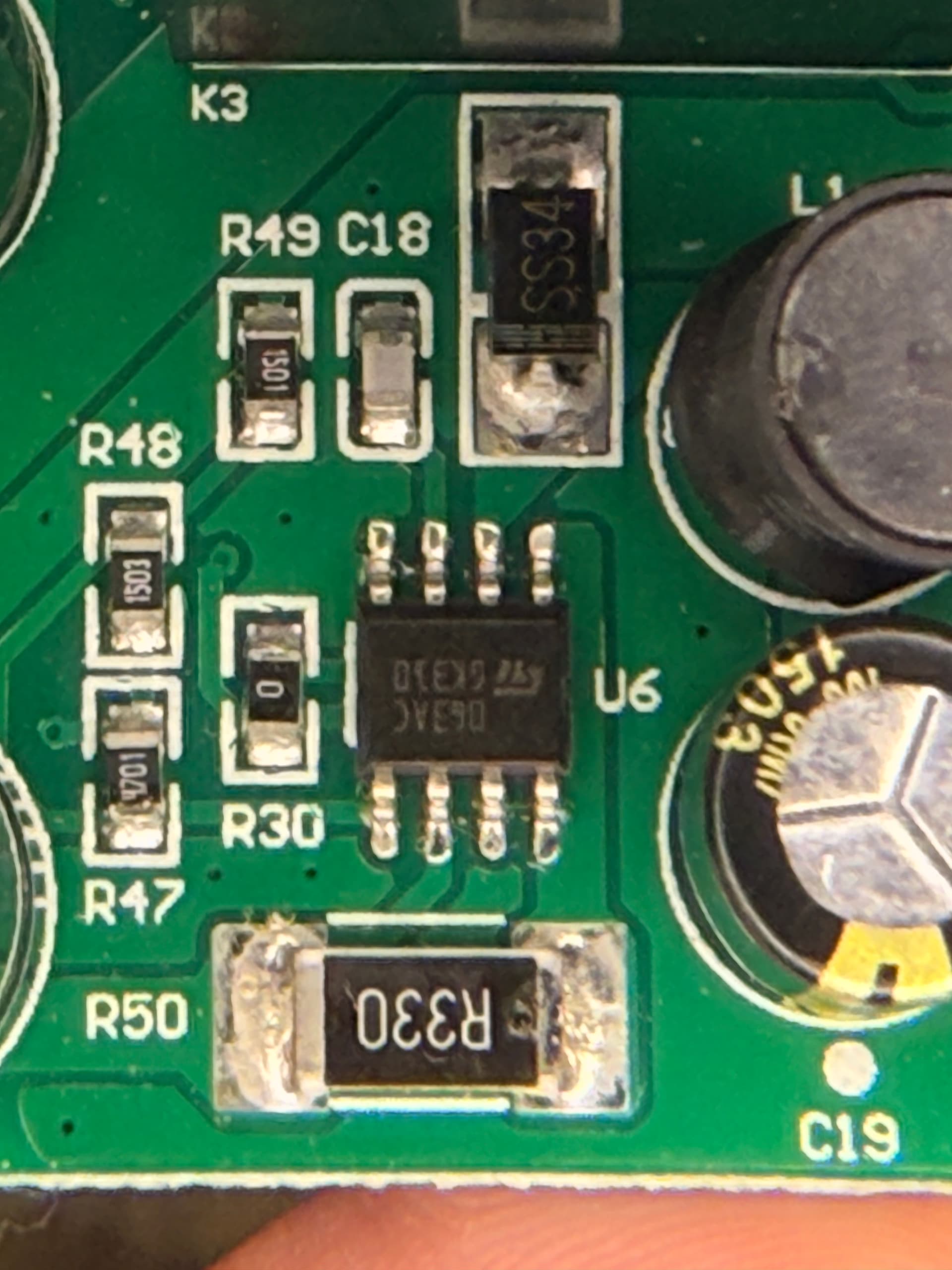
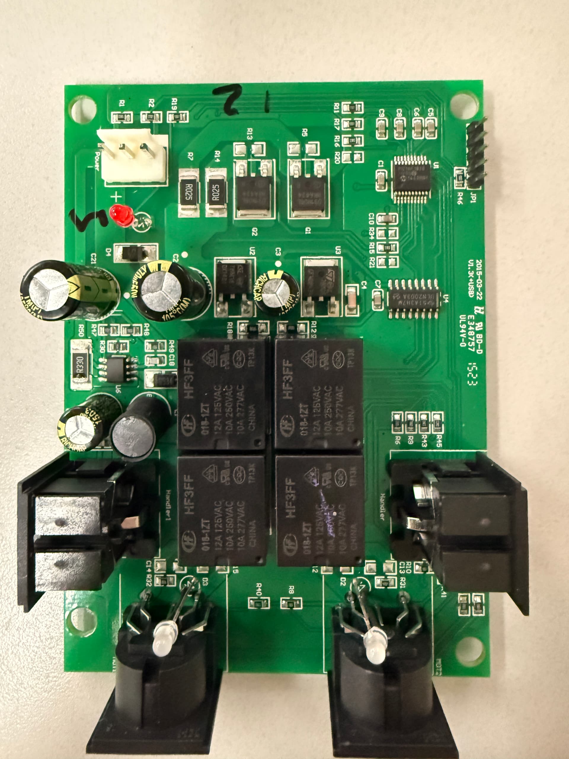
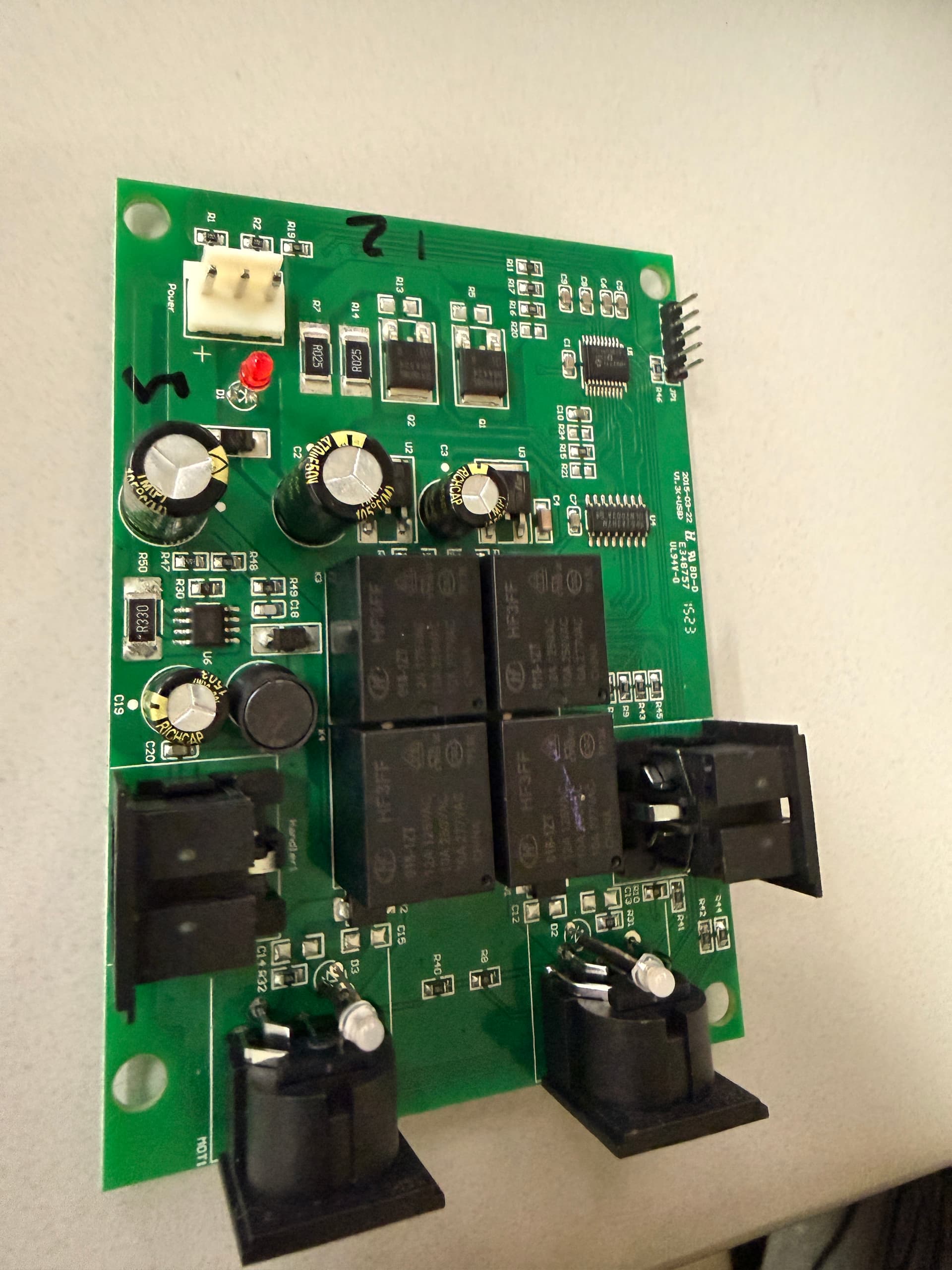
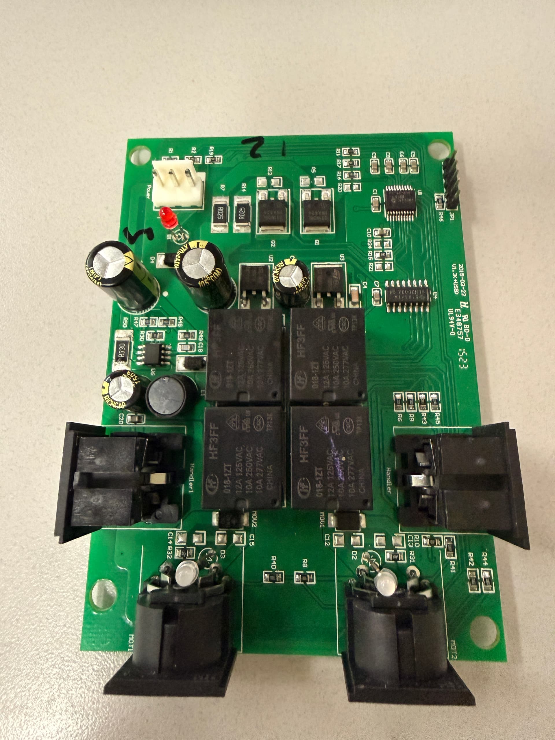
The power supply regulator, the MC34063AC, seems to support around 1 amp or so, so should be able to supply enough current to power an external addon ESP32 as well as the low voltage component needs of the controller board. This is supported by the decision to provide an external USB charging port on the end of the remote board - there’s obviously power to spare. The ESP32 will only need half an amp or so maximum, and will be in idle mode most of the time.
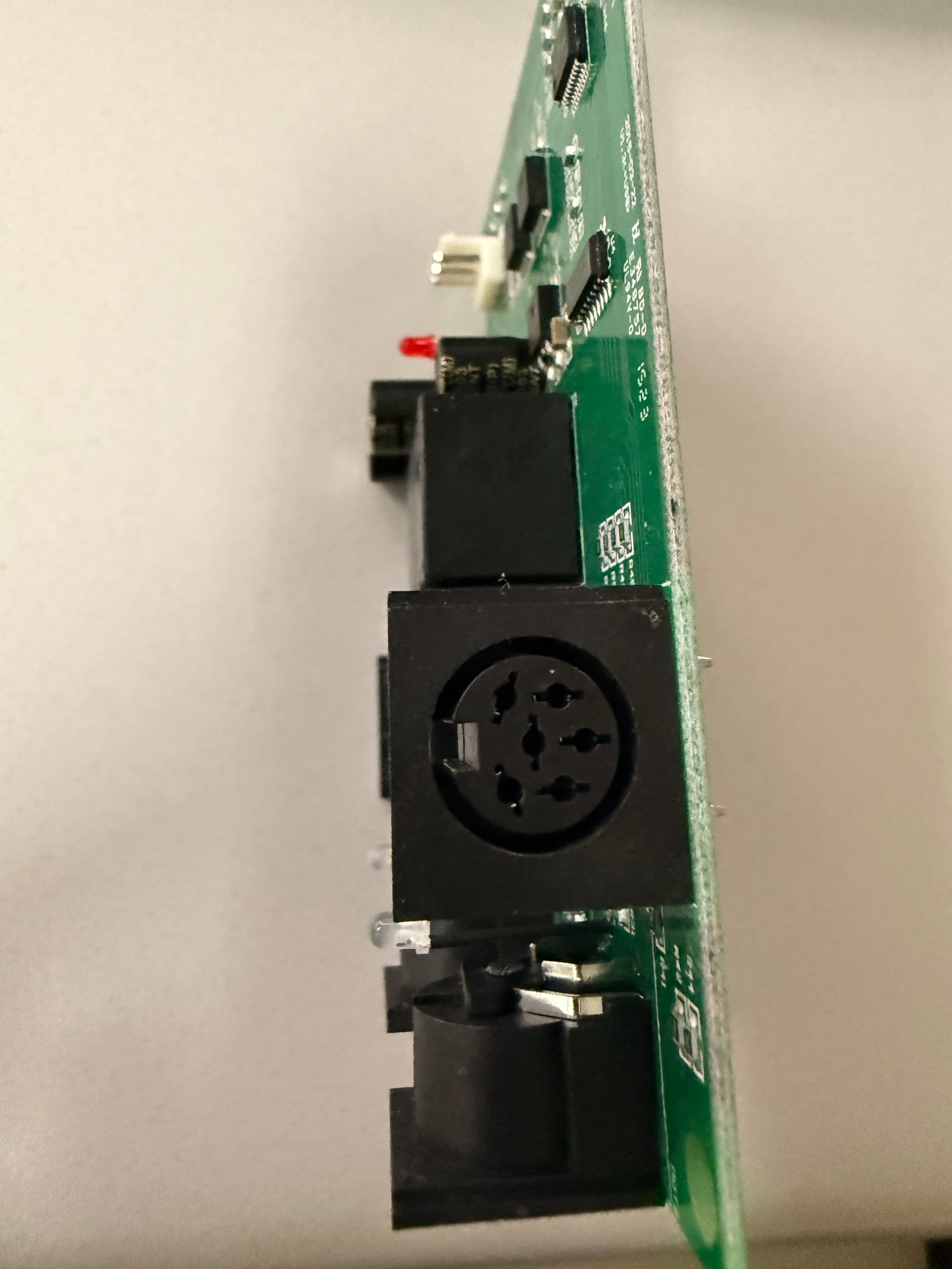
I envisage your final result will be a small box plugged into the spare Handler port using a suitable plug, powered by the USB 5v pins, containing a ESP32 and a transistor and a few resistors for voltage level matching and driving the TX and RX pins. Whether you go with ESPHome or Tasmota for the software side of the controls, going direct or via MQTT, will be another step.
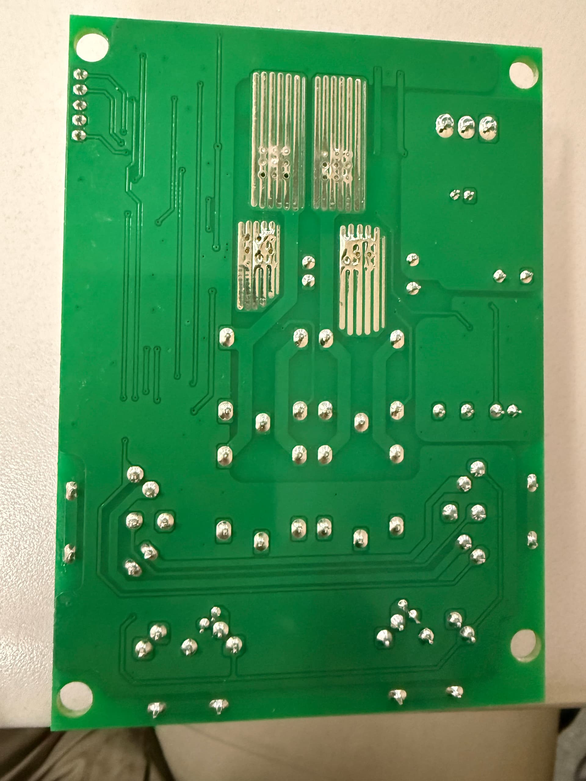
Interesting use of PCB tracks on the rear for what appears to be heatsinking for higher current semiconductors and resistors. Obviously not a first generation version of the circuit board…
Basic question: When you press 1,2,3,4 or 5 via the remote buttons, and also using your temporary UART interface, does the controller board LEDs flash adjacent to the 5pin DIN actuator connectors?
Do the numbers transmitted continue after the respective remote button is released? Did you observe a minimum number of transmissions issued? What happens when you press two buttons at the same time? Does it add the values, intersperse them and send both, or what?
What is the voltage at the power pins for both PICs? 5v? For both remote and main boards?