What I added in my design, is a 1000uF capacitor that helps the device get over handling power spikes for some smart meters. I know one case where a smaller capacitor was required to make things work. No success guaranteed, but definitely something you can try. It all depends on the exact power characteristics as provided by your smart meter.
The capacitor must be connected over the 5V pin and the GND pin of the P1 meter connector. From my design:
P1PWR on pin 1 is where the 5V is provided.
GND on pin3 is the ground pin to use.
The capacitor is connector over these two pins (I use some jumpers for enabling P1PWR use and for enabling the capacitor, but eventually this is the connection that is made for the capacitor.)
There is also a data GND on pin 6, which in my design is connected to pin3. This might be the case in your device too.
During the time after my last post I did a couple of experiments:
Took a spare 470nF (did not have a 1000nf lying around) capacitor and added it between 5v and GND. I think that’s the same circuit as you described. But it did not help. same pulsing red LED. I was unsure if that is needed because in many posts that I read I saw the capacitor mentioned only for DSMR4 or lower. and here I have DSMR5.
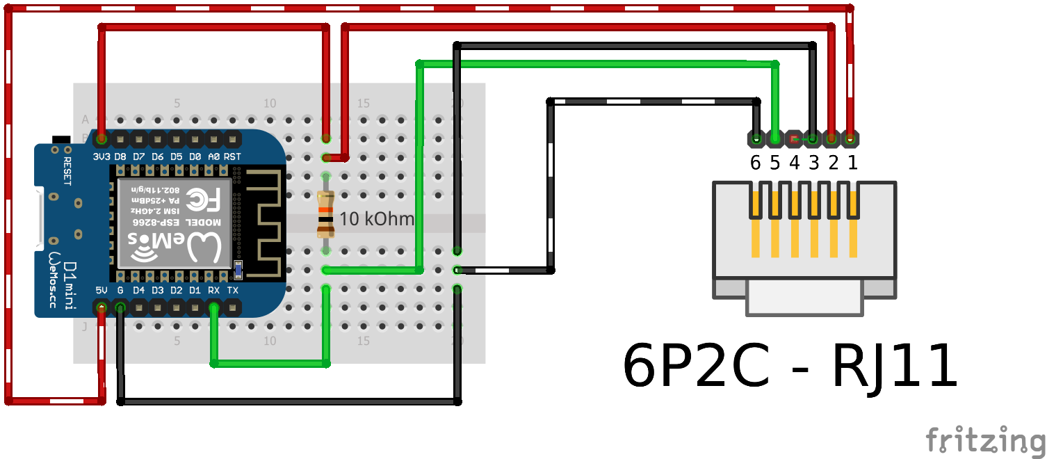
Then it hit me. The product I bought has a very primitive circuit, I even found it online . so I took a spare wemos D1 mini. cut off the rj12 jack. Wired it up: pull-up resistor for Data, grounds connected together, 5v, Data_req to 3.3v. And voila! it works! After wasting a lot of time with a smartgateways product that got me nowhere, I went the dilettante DIY way and got the result…
It is now has been stable for a couple of days.
Only two problems I see:
When I upload a changed config from ESPHome wirelessly, it installs, but Wemos does not reset (I have to go and physically press the reset button). Not sure if this is normal for Wemos (I am new to ESPHome). If someone could confirm this is true I would probably look for another board that resets properly.
Also I am considering swapping it with Wemos D1 mini Pro (because the one I used shows between 86 and 90 -dbm).
Also unsure:
Whether adding more circuitry is needed.
If I want to control the Data_req pin. Right now I am receiving the data every minute.
Nice work on the hack You are right that the capacitor is not required for a v5 meter. But the oscillating light seems to indicate lack of power somethow. But… not something to focus on now you’ve got an alternative going.
About the data request pin
With a telegram frequency of 1 per minute (which is quite low for DSM v5 in comparison to others that I have seen), there is no need to control the request pin. Controlling the request pin is mainly useful for decreasing the frequency.
Increasing the frequency is possible, but when going beyond the default frequency, the smart meter might just start spitting out duplicate telegrams and no new data.
D1 Mini after-flash behavior
I use D1 Mini’s for my DSMR reader board, and I can upgrade these OTA without issues. After flashing, the D1 Mini restarts with the new firmware, without having to do a manual reset. So that is definitely something you can look into.
I don’t think you really need more hardware.
In my design, a signal inverter is implemented for flipping the serial signal. In your config, this has been handled by the inverted: true option for the UART Rx pin. So hardware signal inversion versus software signal inversion. This feature was not available when I designed the circuitry, therefore I had to do it in hardware. These days you can choose what to do.
Other features in my design are a jumper to enable DSMR v4 support, a jumper to enable powering from the P1 port or not and the request pin driving circuitry. These all are not required for your current use case.
I know it’s an older post, but some things that got my attention were: The circuit you bought was an esp32. This normally draws too much power in order to be booted directly from the P1 port. After that you seem to have used an ESP-8266 which is using considerably less power and therefor is able to be powered directly from the P1 port.
Another thing that might go wrong is that the connection on the board you bought is an RJ11 connection. RJ11 only has 4 connections, so most likely the 5V coming from the meter was not connected. On your own setup you’re talking about an RJ12 connector, which has 6 connections, so here the 5V is probably connected. That could explain your experience.
Thanks for your thoughts. But I would like to clarify some of them:
I have read through some threads here and elsewhere and saw reports that with an appropriate circuitry ESP32 can be powered through P1.
I also saw the description of the product that I bought that clearly stated it’s ability to be powered through P1 and that it works in Lithuania.
one reason I chose a complete product was the hope that if someone is making such claims, has verified that the product actually works. also it is made in bulk so it should be better tested than whatever one contraption I might cook up
It turned out that the thing does not in fact boot on P1 (it tries (so 5v actually is connected), but fails).
Not to mention that the ESPHome script provided with the device also did not work. had some help from other fellows in this community to make it work.
The connection on the board of the product is in fact RJ12 (6 contacts) not RJ11 (4 contacts), I also used proper RJ12 (6 wire) cable and jacks when trying the product.
And the fact that ESP-8266 does boot and works, confirms the Power issue You mention.
Anyway my Wemos D1 Mini has been working well since last March (the same contraption with Wago nuts ). The only problem I have is weak wifi signal. Which means I sometimes see the lost connections. And since I use the data in some power load handling automations I am taking steps to mitigate this.
I ran a POE LAN cable to that corner and plan to switch to Lillygo T-internet-POE with ESP32. that way I will have my own power and wired network connection at the meter.


