try adding
#include <ctime>
to the top of logger.cpp
try adding
#include <ctime>
to the top of logger.cpp
it is possible to just use ESPhome as a cover, add in the position sensor etc, and have each blind have its own wifi etc. the issue with those really cheap esp32-c3 is the wifi is terrible, im lucky to get 10m with them! and like mentioned before you will lose the speed control and calibration.
the way the code is written its not really possible to use wifi instead of lora. the lora is so integrated to the code as it controls the waking up of the device, encryption, message structures and everything.
Ok I did that, now new errors… not sure why, so I did a pastebin of the terminal output so you can see whats going on.
might need to check the status of the external libraries and dependencies etc,
looks like there is quite a few things not working properly!
perhaps the ai chat in vs code will help? i used that extensively when i was writing the code, and it helped me a bunch… this project would never exist without it.
yes its listing 6 or 30 problems… the AI is not helping… keeps telling me to insert the #include <time.h> but you have a sys/time.h already there…
I am at a loss here… wow… this is not my expertise…
AI just keeps running in a loop… something todo with this time.h
do you recommend me uninstalling vs code completely and going through the steps to get it installed fresh…it was used for other projects on other platforms a while ago.
Jason
clean install on a new pc fixed it… it compiled and i was able to download… sorry again… now comes the fun part…
Jason
All good, im glad you got it sorted!
It really is a load of work printing everything, assembling all the modules, then installing it all and connecting all the cables. even crimping those tiny jst crimps on is painful.
but in the end its nice to sit down and say "i made that… "
how many do you have installed in your home, and have they been reliable? I am not interested in sla printing, I have a few FDM printers and tried printing with .2 nozzle with high quality and it seemed to do ok, one gear cage broke as I was inserting the pin, but I bought some jeweler drills, I think that will help get the holes the correct size for the pins. I think I will just power the whole thing with 12v and drop it down to 5v right before the master device, and then I can re-tap off the 5v again if I have a larger window with more than 4 units slaved. Im curious what the other people thought for type of filament to use. I know ABS wont work becuase of the sun, maybe ASA? or something more exotic? Any other followers care to chime in here?
And yes those connectors totally suck, I hate them so much. If you dont crimp them perfect they will have issues later on. Its so bad for me I just buy pre-crimped ones and solder on the wire.
Also do you have any idea how much current the device pulls at max, like while moving on a difficult shutter? I want to make sure I size out everything correct in terms of current.
thanks
jason
Sorry two more questions…i have two heltec wireless sticks… one is setup as gateway and HA sees it all fine. I have a second that I have loaded the master code onto. I got the keys file and loaded it onto the master, and set the wifi, its not showing up in HA. They are about 4-5 feet apart. How do I get to the web interface again? It seems like wifi is turned off. Does the user button on the device do anything? I dont have PCBs yet, so your button isnt there. I see the white led flash on the gateway when I power on the master. Any ideas why its not showing in HA, I let it go for 5 minutes, still nothing. Blind count stays at zero. I did not do the open and closed limits, but I think I need to know how to get back to web interface to continue to edit settings. Is there a lot somewhere on the master that shows whats going on? Using meshtastic serial logger on the master, it looks like its connected to the gateway but nothing new shows up in home assistant. Also i tried shorting bottom corner pin to ground to simulate the swithc input on the master, and nothing every changes in the serial monitor and the wifi doesnt turn on. As a note, my heltec is the one with the tiny screen. I think the pinout is the same. Any advice?
Ok I got it MQTT port was wrong… I did change it once and it went back to the wrong one… Im better now… thanks… this is great.
thanks
jason
sorry i missed the notifications on the last couple of posts…
the best way to see whats happening is to connect via usb and see what the text in the terminal says for both units.
i did at one stage have a dozen of them all running nice, but over time they have gone brittle in the sun and the cleaner or my wife broke them, so im down to 2 now… the ones above the stairs where they cant reach! the normal breaking point is either the clip to the rail, its super thin but needs to be for the blinds to close. or the end snaps off the actuator - i think thats from it hitting on the fly screen if its not refitted properly. or cracking around the opening for the gears… its a bit thin and could do with beefing up a bit.
for now i dont really have the time to tinker with them… one day ill look at redesigning for injection molding, hopefully that will solve the issue
Hi Chris, Love your project. I ordered some 3D printing parts from JLBPCB using the STL file you shared on GitHub, but they’re telling me some parts are too thin. Do you think I need to modify them?
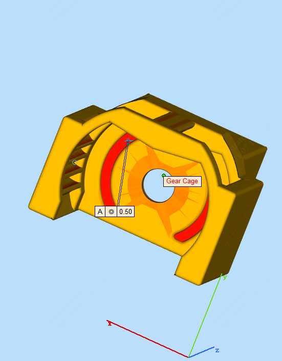
The wall thickness of those indicated red areas is too thin, which has high risks of loss, deformation, crack, or damage during the printing process.
Could you please confirm if the risks are acceptable for you?
If not, could you please kindly increase it to be at least 0.8 mm to proceed? 1.5 mm will be better. Then we will activate the ' replace file' button for you.

Besides, the part has high risks of deformation and warping because of the geometry. Could you please confirm if the risks are acceptable for you?

Usually, for long parts, flat parts, frame parts, enclosures with no strong ribs inside, and large unoccupied areas parts, the models will meet potential risk to shrink to the center or warp to the diagonal lines and edges.
I also use JLCPCB to print these parts, and I’m using the STL file that Chris shared on GitHub, but I’m getting some issues with JLCPCB. I’m wondering if you’ve thickened the parts?
Is there a way you can post some pics of the parts that are having issues? i would like to make this work and I may have some time to beef up some of the files/parts that would need it. You were so close. It just feels like material issues now.
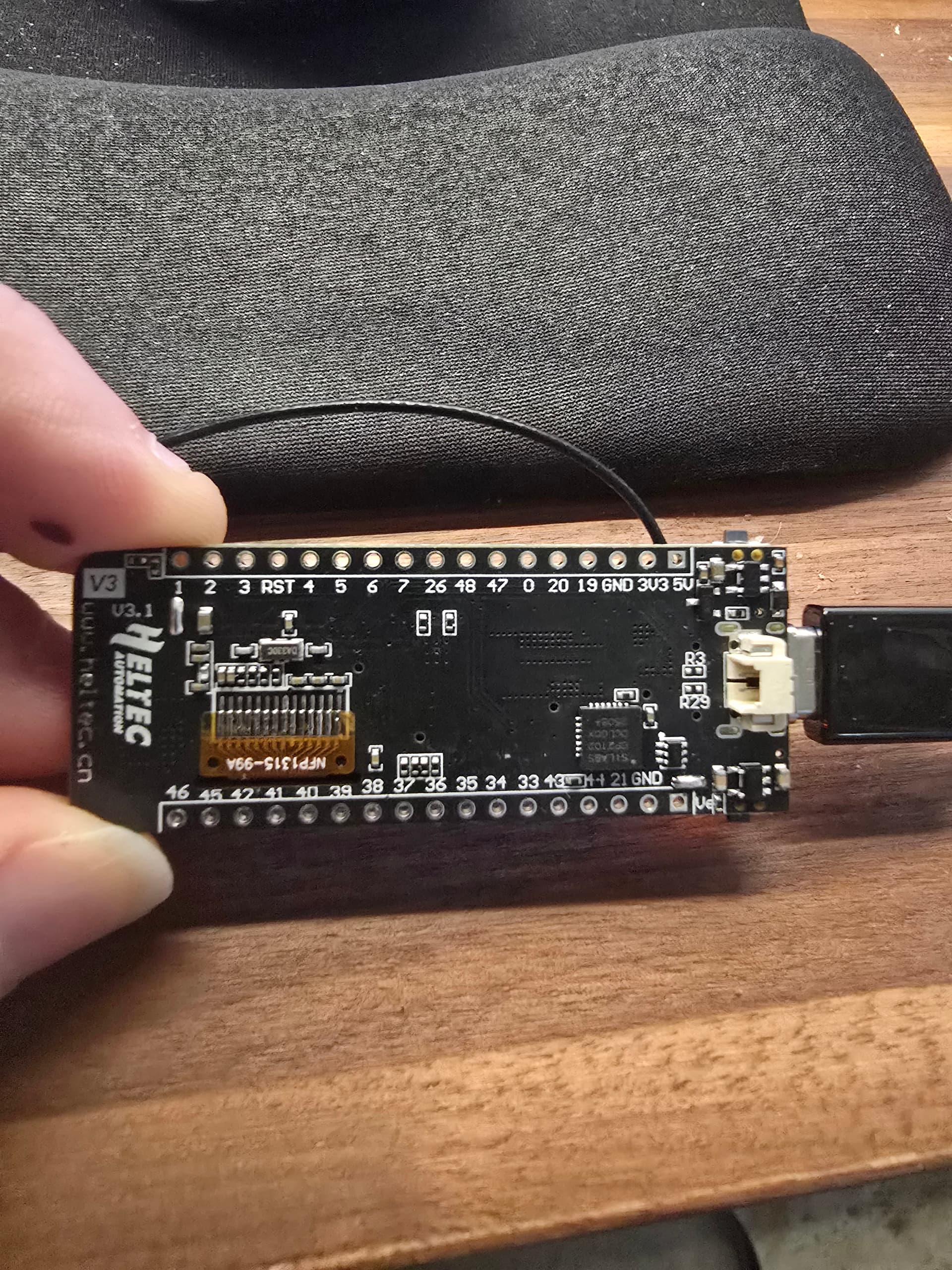
Sorry one more question, you had a lead that was soldered directly onto a voltage regulator on the heltec, is that still required with the latest PCB? Reason I ask, the bottom of mine does not have that same component. here is what the bottom looks like…
Oops two more questions… the boost power board has some solder bridges on the back that look different than yours, what is the desired output voltage? The motor driver also has one pad that can be bridged, is that needed?
Thanks
Jason
So the solder wire directly onto the mosfet, I am stuck at this step. Can I just connect to the battery connector? My board doesnt seem to have that mosfet in the same position, as shown by the image in the last post. What should I do at this point? Thanks
Jason
Sorry i don’t seem to be getting notifications… the thickness of the parts is thin due to the short length of the shafts, i wanted as much as i could in the gear as it needs to transfer torque, those red areas are only stopping the pins falling out and there isn’t much force on them. as for the long parts, yeah they are possibly going to warp, that why i specifically print them without the normal angles people resin print at, but they need to be that thickness/length to serve their purpose… i cant make them any thicker otherwise they wont fit between the frame and the shutters.
if i was going to beef anything up it would be the base, i would make it 0.5mm thicker, and i would make the end plate near the motor 0.5mm thicker too. there is also the slot where the antenna slides into, it goes all the way to the end plate at the moment but i would bring it back 30mm to reinforce over the opening where the gears come out. these changes are based on the failures i’ve had, from the cleaners forcing them when cleaning. the issue is when using resin the different thicknesses shrink differently and we don’t want to introduce twist by making parts thicker along those long edges.
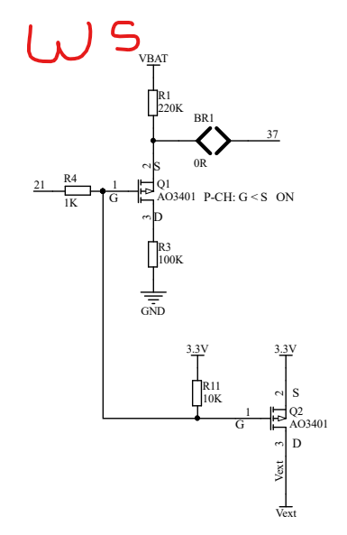
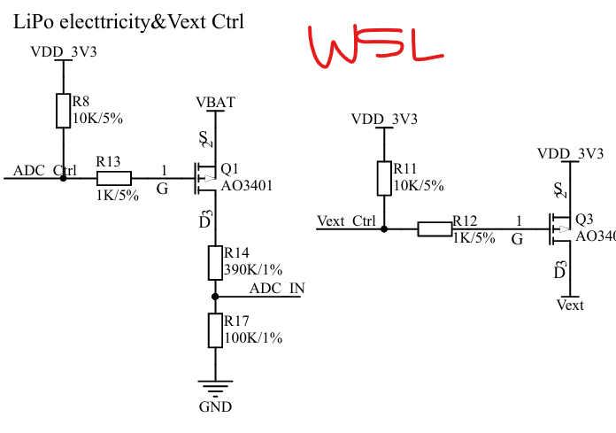
i’ve just checked the schematic and there is a difference between the wireless stick and the WSL. unfortunately the schematic shows it wont work.
on the WSL the mosfet is connected directly to the battery +, and the voltage divider is between the drain and gnd, on the stick you have the divider is between the batt and the source of the mosfet. this means soldering onto that pin of the mosfet is going to try and pull power through a 220K resistor so it just wont work.
the other difference is the WS doesnt have independant control of the vext mosfet like the lite does, this means there would be a lot of work patching those functions… we use them for power saving on the rs485 chips
Ok thanks, I only ordered 2 of the heltec with the display. I know i can use one for the gateway. I ordered a few of the correct versions, like your project uses. Where does the power connect to on the master unit? Usb C? What voltage can I give it max?
Thanks
Jason
Have a look at post #221 shows where to hook it up. This feeds back to 5v
I forgot you are doing continuous powered units, you don’t need to solder onto that MOSFET as you feed back into the 5v rather than switching the battery to power the slaves.
I’ll have a look tonight how best to keep the next powered on.
OK thanks, yes I will be constant powering these guys with 5v, so if I dont need to solder onto that mosfet even better. Do I still need to turn on the motor driver somehow?