Smartening Plantation Shutters

Awesome work, i like the idea of having a means to wake the wifi module as that, like you mention, its the biggest drain on the battery but near instant controls is required for sure.

One of the biggest constraints i have is the width, there is only 24mm between the inside of the frame and the edge of the louvres when they are open, this has been the biggest challenge. I also want to have the actuator on the hinged side of the panel - so the standard clip on a louvre wont work because of the bar that links the louvers together (and i think the clip may limit the amount they close and let more light in). This is why i have stuck with the n20 motors, as there torque to size ratio is so good. I have found that slowing them down does make them noticeably quieter, and the biggest difference was applying a PTFE dry lube to the shutters, this reduced the load and noise considerably. with this design there is a changing amount of leverage too, so its only the initial opening where its noisy.

Like you and probably many others there is often a whole house of these things, and the cost when using the off the shelf ones will add up quickly. hence why i want to use cheap off the shelf components and modules from china for initial build myself designs. I will use some perf board initially for some pullups and caps, perhaps in the future ill design a small board with motor driver, current sensor and the components required for the encoder and button. The wifi modules vary in price quite a bit and i haven’t found one i like yet, but since you mentioned the lora I found the Heltec Stick lite V3 that would be absolutely ideal for this, and also includes battery management. To reduce the number of wifi connections i will just use 1 master and several slaves, linking them together with i2c as the maximum run will be <1m between nodes, in this case a much cheaper micro could be used at each actuator… this way the slaves can use a significantly cheaper mirco without any battery stuff, i was thinking a d1mini in each one with wifi turned off - but having the option to turn it on via i2c for updates.
rough prices from aliexpress, not including shipping/taxes
encoder $0.20
tactile $0.05
drv8833 motor driver $1.00
i2c current sensor $1.50
n20 motor $1.50
magnets $0.10
battery terminals $0.60
Resin $3
heltec lite v3 $33
D1 mini $4

A whopping total of $40 for the master and $10 per slave… that’s what ill tell my wife anyway… i’ve probably burned through a bottle of resin already prototyping and spent hundreds on motors, modules and components that will probably sit in a draw. not mentioning the number of hours designing

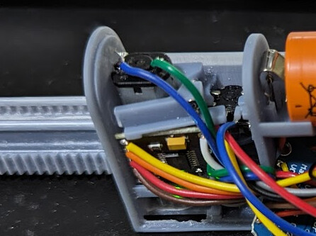
I’ve been working on another new version that should allow for significantly more room for electronics, and will also include an 18650 holder. I’ve also put loads of effort into making it quick to assemble. I’ve removed many of the limit switches, just the one that is on the rack the motor drives, the rack is magnetically coupled to the actuator arm. there is a mouse wheel encoder on the actuator arm to detect position and any manual movement and weather the magnet is linked or not. Because i want to make this thing easy to assemble and solder the tactile switch and encoder just clip in in a way where the wires can be pre-soldered or even easily soldered once installed, the motor driver will just sit in a groove and the motor clamp will hold it in place with just a single 2x8mm screw. this is still a work in progress… i haven’t even got to the teeth on the rack yet. The body is 22mm x 44mm x 110mm. and the actuator arm is 230mm long overall

I found resin on resin is just too much drag and with clearances big enough to reduce drag it gets sloppy, it also requires significant lubrication which will probably require regular maintenance. A notable change in this design is to use 1mm dowel pins as linear bearings, i will play with the size and see how reliable it is. With the transparency turned up you can see the recess where a 16mm long dowel sits captured, it then sits in the grove of the moving parts holding it in place. I have ordered a small kit with m1 and m1.5 pins of various lengths, the 1mm gives 0.5mm to the outside edge, if i change to 1.5mm it gets pretty thin at 0.25mm. buying the precut and ground pins will probably work out to about $1.50 per unit (6pce)

That is definitely a bit tighter than mine. Mine used a NEMA11 which is like 28mm and I have a bit more clearance than that. And you are 100% correct, my (borrowed) design does let a little bit of light in which is annoying. Do you maybe have a video with the tuned down n20 motors so I could get an idea of how loud they are? Perhaps a different motor driver may help with noise too. I completely understand trying to keep it as cheap as possible but I personally would be open to a slight increase in price if it’s not super loud.

That’s the one I prototyped with, somehow forgot to add a link or info in my first post. You could drive the cost even cheaper by just getting the LoRa modules that the Heltecs use (SX1262 or something similar) and adding to D1 mini, but that’s an extra assembly step that will surely get tiresome when deploying across the whole house. The Heltecs have some sample GitHub code with the LoRa wakeup code, but their dev environment setup was a pain. I ended up porting it to new libraries that aren’t Heltec.

My wife keeps asking me too what I’m going to do with every new box of crap that gets delivered for my new prototypes.

Every iteration of your design looks better and better!

Unfortunately i don’t have a video showing the volume change at different speeds… and I’m away from home for the next few weeks.

I did do quite a bit of testing with it, trying to find the optimal torque vs speed. there was two things i played with, the PWM frequency, and the duty cycle. from memory it was harder to detect stalls at the lower PWM duty cycle because the current draw was too low, and varied with battery voltage just as much as the load varied. post 28 has the code… so it must have been around then when i was playing with this.

the width limit is only on some blinds, and is a combination of width and height, the gap between the louver and the frame is around that 35mm gap, but the ones fitted on my narrow 500mm wide windows have been mounted in front of the window recess, and the recess width is causing the limit. I think they do this so the louvers are bigger and let more light in, if they were inset to the recess the louvers would be 50mm shorter. I guess that equates to 10% more light.
this photo is taken from the window side, with an old version that was actually 26mm wide… so maybe its not as tight as i thought it was. it also shows the clash is only at the top of the cover. ill have to check the other frames but i thought this photo was one of the tight ones.

and a little more progress on cad

With your Heltec Stick, did you run ESPhome on it? and have custom libraries in ESPhome? or did you just go with arduino ide?
my plan was to use ESPhome and the simple ledc component for pwm speed control of the motor, and the rotary encoder sensor component for position sensing. I also need to have the rotary encoder pins wake the esp too, this way i can track position. hopefully the wakeup doesn’t take too long and make it lose position. my calculation is 1 pulse per 2.3mm traveled so its not going to have super precision… about 2.5% steps. i just reduced from 18 teeth on the encoder wheel to 12, surprisingly this changed from 5% per step to the 2.5%

This looks like it might be a good off the shelf solution for those using zigbee

I went straight Arduino on the Heltec Stick for the window nodes, way more flexibility and control plus I wanted WiFi disabled and ESPHome doesn’t seem like it was really built for that. I think for my gateway node I could probably use ESPHome, and I probably will, but I haven’t gotten that far yet.

With regards to the wakeup time, it’s really fast, but I guess I don’t have anything to compare it to. Maybe it depends on how fast someone is opening the blinds. Feels like no matter what if it’s sleeping it will miss some (maybe a few) encoder steps while waking up, but you can probably code around this by recording “last known” and on wake immediately start to measure current position in order to calibrate it. I don’t think you’d be able to recreate this logic easily if you were doing ESPHome on them though. Interesting to note that the AM20 uses a rotary magnetic encoder as well and never loses track of shutter position somehow.

I did play with these. I chatted with the seller on Alibaba and it’s basically just a Zigbee to RF converter that sends commands to the shades, so I doubt it would have positional shade control (just open/close). The battery life is really good though, several months and probably longer if the solar panel is hooked up. The pricepoint doesn’t scale very well though, but you can always negotiate for bulk deals.

1 Like

Ah good catch, I was about to grab some of these with the idea they they were actually zigbee versions :frowning: I guess maybe not now.

I did have an RF roller blind some time ago and used to use this HACS plugin to be able to set the % opened, but it looks like its been archived by the maintainer.

A little more progress, most of the design is complete, just needs some fillets applied so it prints cleanly


I’ve added a couple of little clips to hold glass reed switches so i can detect when the panel is opened and close the blinds. I’ve put them close to the base and on the back of the battery holder, i think having the options will make it easier to find a good spot for the magnet position.
There are cutouts for 4mm cable entries at both the top and bottom, with just a thin window to pop out if you want to run a cable in.

Any other feature requests?

a couple of things I’m thinking would be a motor gear cover to stop wires jamming it up, and some mounting boss’s / holes

2 Likes

Thst’s exactly what I was looking for - thank you!

1 Like

I’m discovering that I’m in way over my head with the whole Lora thing, and i really love the ease of ESPhome and the cover components. I still really think using Lora to wake the ESP is a good idea allowing faster control of the blinds and saving power by sleeping and not being connected to Wifi all the time.

After days of searching i found this set of libraries for ESPhome, and an example
https://github.com/u-fire/ESPHomeComponents/blob/ef633b3a198fd308f82e04239cc9cdbdc9763253/example_sht3x_lora.yaml

The libraries seem to work for publishing sensor data via a lora to mqtt gateway, It would be awesome to add data going the other way, and also using the wakeup functionality by putting the Lora in receive mode with an interrupt before putting the esp to sleep. i dont know if this could be done with a small modification to the gateway to subscribe to a mqtt topic and transmit it, and then a change to the device side library to also listen, perhaps just a cut and paste from the gateway library. i did see some code somewhere that changes the setup function for the lora module depending if the device was waking from interrupt or from power up, this meant when waking from interrupt the module wasnt reinitialized allowing the data to still be read when the esp wakes up.

so basically when we want to control the blinds we can issue the command via mqtt, the gateway converts the message to lora, and transmits, on receiving data the receiver wakes the ESPhome device, esp reads the message and if its a command with position it will stay awake while it opens the blinds and send status updates via Lora before going back to sleep.

a switch could be setup to enable wifi for software updates, just send a message via mqtt to wake it up and turn the switch on. this would be great for performing firmware updates via a phones hotspot when devices are too far for normal wifi.

if the blinds are manually adjusted the encoder could wake the esp, monitor the position and also send updates via lora.

I think ESPhome does work ok without wifi as long as the watchdogs are disabled, api has reboot_timeout and wifi also has reboot_timeout. there is also the wifi enable_on_boot that can be set to false, hopefully this will make things quicker when reading the encoder and limit the missed steps

1 Like

This is exactly what my PoC code does in the video that I posted. I can share it with you if you want, but I can’t share the wiring anymore because I dismantled it for other projects. IMO I think trying to stay in ESPHome land will make it more complicated in the long term and won’t net you the real deep power savings you can get by writing custom code and using LoRa as a wake mechanism and putting the ESP32 to sleep. I was considering the MQTT gateway route too which I think Home Assistant could just pick up the devices and automatically import them as covers. But then you got my ideas flowing with regards to the mechanism physics and I started playing with 3D printer designs and forgot about the software side. I’ve been playing with using a servo to drive the blinds but in my test it wasn’t easily back-drivable which brings me back to using a normal stepper motor without gearing, but I’m wrestling with the price and extra complexity of needing a stepper motor driver and thus more complexity/circuitry.

Waking up via encoder is another problem I’ve been trying to solve. If you use a potentiometer as an encoder you’ll have to leave an ADC running all the time which will chew up battery. I’ve been struggling to find another absolute encoder that can trigger an interrupt to wake up the ESP32. Perhaps with some clever time-splitting I can just wake the ESP32 up once or twice a second real quick to check the encoder and see if it’s moved/moving and then go back to sleep. Without WiFi this should be feasible, I think, because the wakeup/go back to sleep process should happen so quickly.

I have been working on the software a bit the last few days after work, to start with I’m going to stick with ESPhome and accept the extra power consumption, having the core part setup like Wi-Fi, OTA and all the other things that make ESPhome so easy to use will make it easier for me to iterate the code. i think getting a concept going for how to control the blinds is the hard part, because of the mechanical override design and calculating the rack position vs the actuator position. after that ill look at taking the libraries back to Arduino if needed

butchering the current based cover component i have added a test to see if the encoder is moving when the motor is moving, and if the deviation goes above a threshold it will reverse the direction and try and get the magnetic link to re-engage. its still untested as I’m still away from home… but it compiles without complaint… fly out day tomorrow so should have an idea if it works soon. i bought a new 3d printer, the Halot Mage 8k, it has a print bed big enough to print the latest design, so once that’s setup and started printing ill start testing the software, all the motor drivers, encoders, limit switches, current sensors have been delivered now, the only thing is i accidentally ordered the Heltec boards with the wrong frequency for Australia, i got the 470mhz not the 915mhz. so initially testing will be done with the pros3 from unexpected maker.

using an encoder to wake the ESP32 is kinda tricky with the current deep sleep implementation too, I’m really confused with a statement in the docs where it says you cant use ext0 and ext1 at the same time - reading the code i cant see why not. I plan to butcher that component too and try changing the ext1 code to have a similar logic to ext0, so i can set one encoder pin to ext0 and the other to ext1, a change on either would wake the esp and i could read the wake reason and infer the direction from that. at the moment ext1 takes a list of pins and creates a mask, and you have two options, all low or any high. i think if i create the mask with just the encoder pin and then read the pin right before sleep to determine if i need “all low” or “any high” which for a single pin it would be the same as the invert function for ext0. however this may make it hard to also wakeup from the Lora module, the only other way i could think of was to not allow the encoder to be in certain states when going to sleep… so moving the position slightly so that the pin is at the required starting state. i don’t know the pulses per rev of the cheap encoders i bought too, I’m guessing its 12 but i don’t actually know until i test them.

i guess the other thing is, what is the likelihood of just moving the blinds a little bit? it will most likely be a big change from open(horizontal) to fully closed, or from fully closed to horizontal… so maybe just one pin to wake the esp and take note that it was manually adjusted will be enough. and if it was manually adjusted it will need to re-latch first before driving to the desired position. with the current sensor i hope to detect an increase when it re-latches and use that to trigger the command to target position

Just now i thought to look at linear potentiometers, there is a 128mm overall one with 100mm travel, which is perfect for the travel required for my design… actually 10mm more than needed. and they aren’t too badly priced at $3each delivered. they would probably give better resolution than the encoder too… the micro doesn’t even need to wakeup when the blind is manually adjusted, it just needs to know the current position when its trying to move it, so wakeup, check position vs last recorded position and it will know how far and in which direction to travel to re-latch. I just ordered 10… so will have a play with them when they arrive… probably in a few weeks. it was tempting to get a motorized one to test out too… but i managed to have some self control

i was considering the use of Lora for control a bit more, if it was Lorawan it would be secure, but as its just low level Lora there is the possibility of replay that could remotely control the blinds… it probably not high consequence but also not ideal. however if its just used to wake the esp, and the the Wi-Fi connects and provides the secure connection, the consequence could just be the esp keeps waking up. perhaps a magic number could be implemented, where it gets the wakeup code via Wi-Fi, and only if it receives that code via Lora will it wakeup fully and turn on the Wi-Fi etc…

as for your steppers, the drivers are dirt cheap now days… like the drv8833 one I’m using for the n20 would work for a stepper… its good for 1.5A, especially for short duration. (heatsinking against the motor body would help too) and just use the accelstepper library to provide a soft start

Nice work y’all.

So i’ve been using these ali express ones as well (these ones https://www.aliexpress.com/item/1005004247653312.html?spm=a2g0o.detail.0.0.72fcJb7NJb7Nan&gps-id=pcDetailTopMoreOtherSeller&scm=1007.40050.362094.0&scm_id=1007.40050.362094.0&scm-url=1007.40050.362094.0&pvid=9994894b-1cd7-4901-9e03-d6b44157133b&_t=gps-id:pcDetailTopMoreOtherSeller,scm-url:1007.40050.362094.0,pvid:9994894b-1cd7-4901-9e03-d6b44157133b,tpp_buckets:668%232846%238108%231977&isseo=y&pdp_npi=4%40dis!GBP!17.39!10.44!!!20.45!!%40211b619a16987050201013985e171f!12000028514597877!rec!UK!3695632495!)

But they are very expensive. I bought one just to mess around with it and also, as they were so expensive, i thought why not add some sort of linkage as most of the time shutters are next to each other. That way if one shutters goes down or up, all the shutters linked go down or up.

I haven’t had the time to mess to much around, as i don’t really want to destroy our current shutters, but it seems feasible as a low tech option ? As the above are like 60,- or so and i’m not going to kit out the house with a motor for every single shutter…

It seems to me that linking shutters is the way to go?

It would be possible to link them together, but it may be too tight for 1 small motor. I found the n20 with the highest ratio gearbox running off a single lipo was unable to move the shutters reliably until I lubricated all the pins and linkages. Also it would be nice to adjust each independent so you can adjust for different light levels.

My idea was to link many to a single micro, but I’m looking at the price of different boards and I think 1 battery and solar charger connected to a wifi enabled micro as the master and then 12 slaves off that connected via i2c. Because of the cost of esp32 modules I’ll probably make all the slaves with them…

Hopefully I can build these for 1/10th the cost of the ones currently available.

1 Like

I think there will be a big market for this, especially considering how little there is for it and how expensive they are (And how inflexible).

I know one thing the other half wouldn’t like (and i’m not too fond of it either) is that it’s not possible to operate the shutters manually with one of those ali express designs. And same for independence, so yes the best option would probably be to have a cheap solution that can be per shutter, to get the most flexibility.

Also, battery on that ali express monster is pretty lousy, it’s about 2 months or so (max). And that added solar panel doesn’t do much :-). Also not sure how they envisioned charging on this thing, it has a single screw hole in the back but no one is going to screw them in their expensive shutters? And that would not be enough to hold the device when it exerts any force. I came up with velcro, which does a very good job and i could pull it off easily to charge.

Love your work, just my 0.2 cents. How long do you think it would take you to finalise this work? Are you planning to sell it commercially/to hobbyists? I for one would be very interested in a solution to this problem.

The design is in onshape, it’s still a work in progress… but it is fully open to be made by anyone. I wouldn’t make it just yet though as it may not work

I got home from work yesterday after a month of nightshift, stayed up for 27hrs , setup the new printer and started it printing, opened all my packages from China, and then slept for a solid 12hrs!

Battery life will always be an issue with wifi, it’s just about getting the right level of sleep and the right size battery and solar panel. A 60mmx 500mm panel would be perfect, but I haven’t seen one that wide. I know 1 side of my house gets limited sun so they will be plugged in instead.

For sticking it on I found the stretchy things for hanging hooks are the best, they hold really well till you pull the tab, and they are cheap

So… clear resin was a bad idea! i wanted to make the first one a bit see through to check the alignment of things, like the tabs in the battery clips and stuff, but clear resin is really bad for anything with dimensional tolerances. so this is a bit of a non working teaser!


but i have discovered a few things, the battery springs are way stronger than the thin plastic and it bends the end outwards so i need to make the walls thicker.
I’m also going to change the latch too, the magnets have no strength in shear, so i put a square boss on the rack that engages a pocket in the actuator, it works perfectly when the blind is closed, but when its fully open it wont dis-engage because of the pins in the rail stopping them spread, because of the way i designed it, it could also pop the actuator off the rail. I do have a solution, the pocket will be on the rack, and the boss on a springy section of the actuator, that wont actually touch the rack until the magnets align, the magnets will hold the boss in the socket, and require higher force to disengage

Tune in tomorrow to see if the next print is successful

3 Likes

Print was 80% success. but learned quite a few things again.

main issue was missing support in the last minute change i made with the magnet area, this meant the recess for the magnet didn’t print properly. stupid mistake - easy fix


there was still just enough of a tab for it to test it out. it engages pretty well but will definitely need the magnet to have enough force to move the blind.

the encoder doesn’t quite sit properly and is not fully engaged with the actuator, should be easy enough to improve. i have confirmed the encoder reads in esphome, and at the expected 12 steps per rev.

the motor clamp cracked, it needs a little more meat around the threads. i wanted to make it springy so it clamped better, but it means when the motor turns it pops out the tab it levers against. another easy fix.
image
the limit switch on the rack works perfect, and the tactile gets pressed at just the right place.
the pins the rack and actuator run on work really well, a little fiddly to install but with a technique i could get them in pretty easy…

it gets pretty squishy in there… going to have to plan the wiring a bit better! this was just connect point a to point b and not thinking about how much excess or anything.

all up was 6hrs to print, 20mins of cleanup, 20mins of assembly and 20mins of soldering. would be pretty easy to get a production line going to speed things up a bit. and a few print optimization’s to reduce the supports and ease of cleanup would make it quicker too

I didn’t print the cover, i want to finalize the base first. one thing is the battery terminals still press the end out a bit. i will need to beef it up even more, ill also increase the shadow line of the cover to help hide any misalignment.

will be away for the weekend and back onto this next week…

Edit: Because I’m at the 3 post limit again!

Still not working as well as it needs to, the latching part with magnets is too hard to operate manually, but also frequently disconnects when the motor is driving. So I’m going back to the mechanism from post #26 above. I will however keep the larger body so there is sufficient space for the electronics, but ill move the battery to its own case, i think it will get too hot in its current location, and the extra space will help with assembly.

@merlinn31 A video showing it in action. to get an idea of the volume I’ve set my google nest mini 5m away, and set the volume to 50%. The motor driver is set at 90% pwm and default 1000hz. I think the other design will reduce friction a bit as there will only be 2 pins instead of 6, which should help to reduce noise further.

3 Likes

We’ve purchased a new house with all plantation shutters around. Really would love to see how this comes along but i might have to get out of my comfort zone to complete this DIY. :smile:

So the new linear potentiometers arrived, so i whipped up a quick and dirty design.


I’ve gone back to the 3 gears that rotate and mesh in and out of the rack


this time i used smaller pins in the outside gears, this makes the gears way stronger, I also made the middle gear with more teeth so it has more meat, and i increased from 0.5module to 0.6module. hopefully this will stop the gears splitting in half if trying to back drive the motor when its not dis-engaged. seems to work better than the previous one, except when its bound up right at the very end 100% open. I’m not sure exactly why, but i suspect its right on the edge of a gear tooth that would normally push the rack in the wrong direction briefly before the gear is free to rotate, I just limit the position sensor so it cant reach the hard stop of the potentiometer and its working perfect. There is way more travel than required anyway, 100mm, when i only need about 85mm. Once fitted to the blinds it will need to be calibrated anyway so shouldn’t be close to the bad position anyway.

I’ve also stripped out all the extras, no tactile buttons for end stops - no need anymore, no current sensor - no need as we can directly infer movement from the position, and the DRV8833 has current limiting built in. still using the PRO-S3 for now, but any micro should work… its significantly less pins now. just the one for ADC, 2 motor outputs, the motor sleep output and motor fault input - which is optional. Also, I’ve found a PWM frequency of 300hz controlling the motor is a sweet spot for reducing noise, and 40% was a good speed for almost silent operation, however this quick and dirty design i didn’t spend much time cleaning up so has a fair amount of friction and requires 70% to move

Using my modified cover library it reads the position from the pot directly into the cover allowing precise position control, and it always knows the actual position of the blinds even when manually adjusted. I’m surprised this isn’t actually a standard ESPHome component. I still need to add some code to rotate the gears back to the middle after each move, should be able to write that tonight once the kids go to bed.

I’m fighting issues with the new 3d printer… its either the slicer messing things up, or the g-code interpretation or a failing LCD… i cant tell just yet! its like parts of the LCD are not masking after they have been used. and the new printer is so slow compared to the anycubic photon mono, I would say 50% slower! the exposure time is 50% more, and the minimum retract is 25% more, and the maximum retract speed is 25% slower. Then i have to drain the vat after every single print because of all the random bits stuck to the bottom from whatever is going on with the LCD or slicer. I wouldn’t go rushing out to buy the Halot Mage to print any of these… oh and the “free” chitubox pro that comes with the printer requires a subscription… so that’s BS too, why would I put my CC details in just to see if the buggiest software I’ve used is any better in the pro version.

edit: managed to get the software side done while waiting at the school pickup and while the kids had swimming lessons! still needs a bit of work cleaning up the code, but its working. here is a short video showing the mechanism in action, with google helping me out so i can take the video! please excuse the huge amount of PFTE spray around the gears… i didn’t do any cleanup on them, just snapped off the supports and wacked them together!

edit 2: a link to the code.
https://github.com/Hootie81/esphome/tree/main/external_components/position_based
copy the files to esphome/external_components/position_based, I always find the built in file editor of home assistant the easiest way to upload files. and the example.yaml is what i used for the video above. still needs deep sleep implemented to be of any use at all for a battery powered device

still some work to do on the CAD design, it needs a cover still, and some mounting points… hopefully over the next couple of weeks ill get it perfected

1 Like